Assembly instructions power base with power tilt – Mayline Futur-Matic Base without Tilt User Manual
Page 3
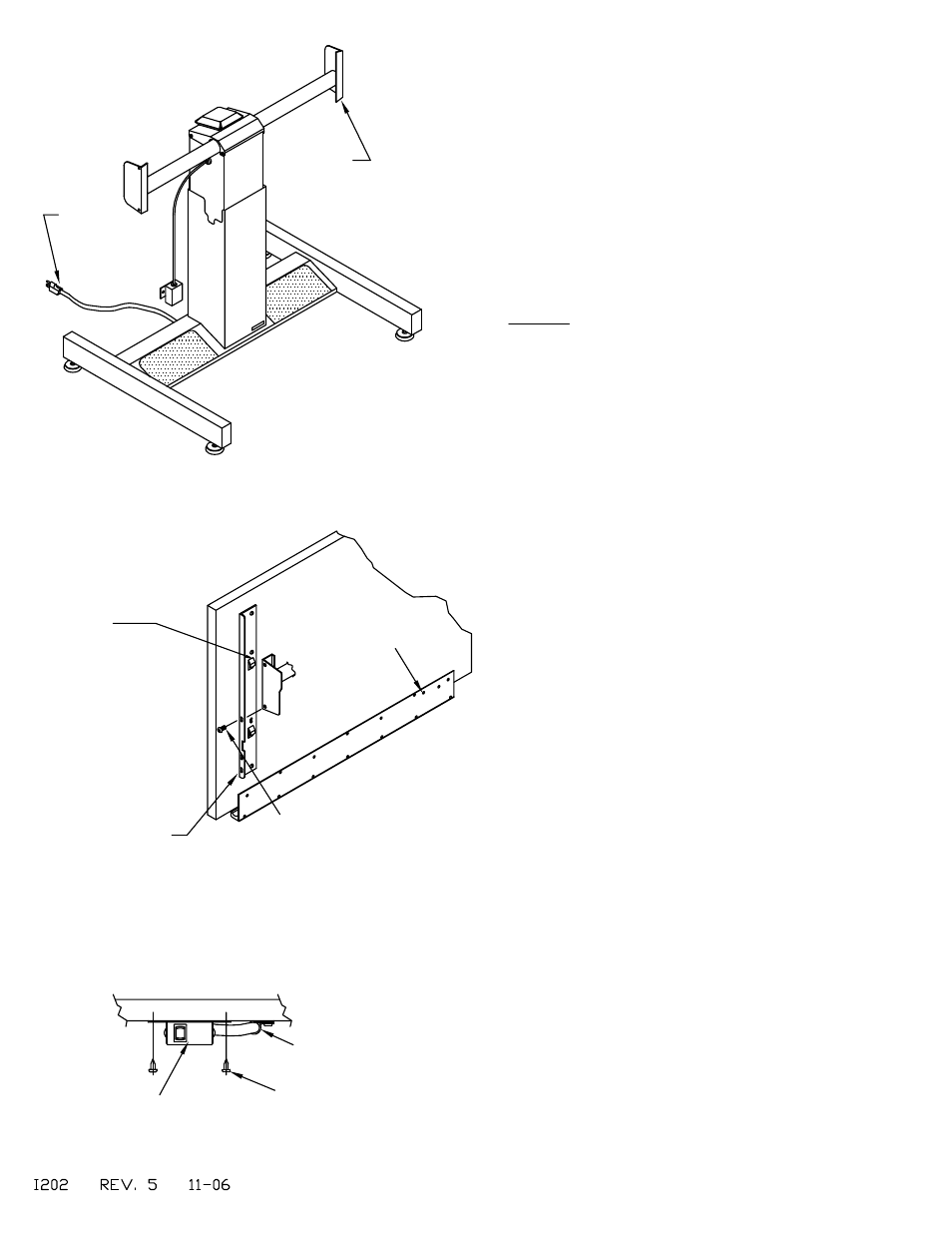
Screw (E3)
Cable Clamp (E4)
Fig. 2
Holes for attaching
Switch Box on Tops
with Pencil Trough
Switch Box
Fig. 3
Note:
Board Brackets may
vary in appearance
per top.
Screw (E1)
NOTE:
Use this hook to
attach Top to Tilt
Pad Edge
Power
Cord (E6)
Fig. 1
NOTES:
Some units are supplied with two R.H. Board
Brackets in applications where a shorter bracket is
required for mounting clearance. Quantity of
Machines Screws (E1) varies by model.
1. Assemble Top and Brackets per instructions
included with the Top.
NOTE: If you are not receiving a MAYLINE top,
locate brackets as shown in Fig. 2.
2. Position Tilt Pads to near vertical position
before installing Top.
3. With the assistance of another person, position
the Top Assembly and hook the board bracket
hooks onto the tilt pad edge. Secure in place with
two 1/4-28 x 1/2 screws (E1) and tighten with
Wrench (E2).
4. Mount switch to underside of Pencil Trough or
Work Surface with two #10 x 5/8 Screws (E3).
Use Cable Clamp (E4) and #10 x 5/8 Screws (E3)
to secure switch cable. See Fig. 2 & 3
5. Attach Power Cord (E6) - 220v unit only.
6. Adjust Glides as required to level.
Tilt Pad
ASSEMBLY INSTRUCTIONS
POWER BASE with POWER TILT
(3)