Assembly instructions power base with no tilt – Mayline Futur-Matic Base without Tilt User Manual
Page 2
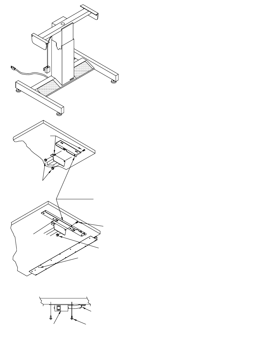
ASSEMBLY INSTRUCTIONS
POWER BASE with NO TILT
1. Assemble Top and Brackets per instructions
included with the Top.
NOTE: If you are not receiving a MAYLINE top,
locate brackets as shown in Fig. 3.
2. With the assistance of another person,
position the Top Assembly and hook the board
bracket hooks onto the tilt pad edge. Secure in
place with two 1/4-28 x 1/2 screws (E1) and two
KEPS Nuts (E5). Tighten with Wrench (E2).
3. Mount switch to underside of Pencil Trough or
Work Surface with two #10 x 5/8 Screws (E3).
Use Cable Clamp (E4) and #10 x 5/8 Screws
(E3) to secure switch cable. See Fig. 3 & 4
4. Attach Power Cord (E6) - 220v unit only.
5. Adjust Glides as required to level.
Switch Box
KEPS Nut (E5)
Screw (E1)
NOTE:
Use this hook to
attach Top to Tilt
Pad Edge
Screw (E1)
Cable Clamp (E4)
KEPS Nut (E5)
Fig. 4
Screw (E3)
Holes for attaching
Switch Box on Tops
with Pencil Trough
Fig. 3
Fig. 2
Note:
Board Brackets may
vary in appearance
per top.
Fig. 1
(2)
- 5 Shelf Bookcase Aberdeen Series (5 pages)
- Bowfront Desk Aberdeen Series (3 pages)
- Contour Bridge Aberdeen Series (3 pages)
- Conference Front Desk Aberdeen Series (3 pages)
- Credenza Aberdeen Series (3 pages)
- Desk Mount Hutch - Glass Doors Aberdeen Series (5 pages)
- Desk Mount Hutch - Wood Doors Aberdeen Series (5 pages)
- Desk-Mounted 20" 4-drawer Pedestal Aberdeen Series (2 pages)
- Extended Corner, Left Aberdeen Series (3 pages)
- Extended Corner, Right Aberdeen Series (3 pages)
- Peninsula Return 60 x 30 Aberdeen Series (3 pages)
- Peninsula Return 72 x 36 Aberdeen Series (4 pages)
- Return Aberdeen Series (4 pages)
- Straight Front Desk Aberdeen Series (3 pages)
- Suspended Pedestal for Credenza - 20" Aberdeen Series (4 pages)
- Suspended Pedestal for Desk - 26" Aberdeen Series (4 pages)
- Reception Counter Aberdeen Series (3 pages)
- Reception Return Screen Aberdeen Series (3 pages)
- 2 Shelf Bookcase Aberdeen Series (5 pages)
- 3 Shelf Bookcase Aberdeen Series (5 pages)
- Boat-Shaped Table – 72" x 36 Boat Aberdeen Series" (3 pages)
- Boat-Shaped Table – 96" x 48 Boat Aberdeen Series" (3 pages)
- Boat-Shaped Table – 120" x 48 Boat Aberdeen Series" (4 pages)
- Boat-Shaped Table – 144" x 48 Boat Aberdeen Series" (4 pages)
- Boat-Shaped Table -- 216" x 48 Boat Aberdeen Series" (5 pages)
- Presentation Cabinet Aberdeen Series (3 pages)
- Bowfront Desk Corsica Series (3 pages)
- Bridge Return Corsica Series (3 pages)
- Center Drawer Corsica Series (2 pages)
- Credenza Corsica Series (4 pages)
- Lateral File Corsica Series (3 pages)
- Pedestal for Credenza - BBF Corsica Series (2 pages)
- Pedestal for Credenza - FF Corsica Series (2 pages)
- Pedestal for Desk - BBF Corsica Series (2 pages)
- Pedestal for Desk - FF Corsica Series (2 pages)
- Peninsula Desk Corsica Series (2 pages)
- Return, Left Corsica Series (4 pages)
- Return, Right Corsica Series (4 pages)
- Straight Front Desk Corsica Series (3 pages)
- 72" Conference Table Corsica Series (3 pages)
- 84"/96 Conference Table Corsica Series" (3 pages)
- 120" Conference Table Corsica Series (4 pages)
- Presentation Board Corsica Series (3 pages)
- Round Table Corsica Series (3 pages)
- Top, Modesty Panel, and Base Leg - Adder Corsica Series (5 pages)