Mayline Futur-Matic Base with Manual Tilt User Manual
Page 3
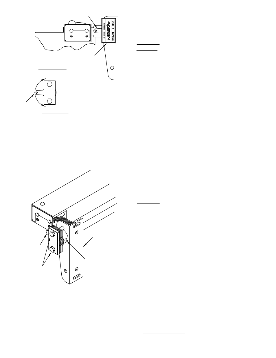
TILT COUNTERBALANCE ADJUSTMENTS:
WARNING: to prevent damage or injury, work surface
MUST BE in Vertical position before any adjustment is
made.
1. Place the work surface in a vertical position.
2. Remove Cover by pulling straight off.
3. Loosen the two Hex Head Cap Screws.
4. Set the Index Lever to the desired setting.
NOTE: An increase in torque is needed as more weight
is added.
5. TIGHTEN SCREWS and replace cover.
Cover
DECREASE
torque
NOTE:
Board Vertical
Index Lever
INCREASE
torque
Index Lever
TILT LOCKING ADJUSTMENTS:
In locked position, brake should be tight enough o hold
work surface horizontally with about 25 - 50 pounds of
extra weight beyond normal equipment. Be user when
checking brake that the work surface is elevated slightly
above bumpers.
WARNING: TO PREVENT DAMAGE OR INJURY, work
surface MUST be in Vertical Position Before an
Adjustments is made. After adjustment, work surface
may then be moved to near horizontal position to check
brake.
1. Place the work surface in a vertical position.
2. Loosen the two nuts that secure the work surface to
the tilt pads (nearest to the adjusting nut).
3. Remove Dial-a-Torque cover pulling straight off.
4. Loosen the two Hex Head Cap Screws.
5. Using an Allen Wrench, small rod or a screwdriver as
a lever, turn the adjusting nut clockwise to increase brake
pressure or counterclockwise to decrease brake
pressure. CAUTION: Having brake set too tight may
damage toggle.
6. TIGHTEN NUTS or secure work surface.
7. TIGHTEN SCREWS and replace cover.
Index Lever
Adjusting Nut
Tilt Pad
Hex Head
Cap Screw
(3)