Mayline Futur-Matic Base with Manual Tilt User Manual
Page 2
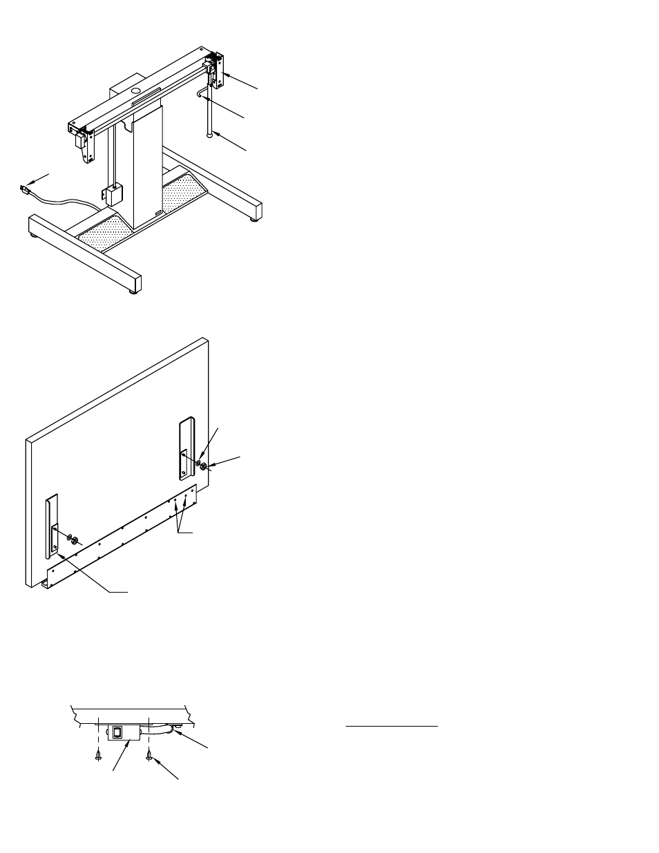
1. Slide Handle Assembly (1) over the toggle arms and
attach it with Rivet (E6) so handle rests in the Tilt Support
(Fig.1). (See Brake Handle / Work surface Positioning)
2. Release Brake and move Tilt Pads to a near vertical
position. Leave brake released until work surface is attached
(Fig. 1).
3. Assemble Top and board Brackets:
A. For products supplied with MAYLINE tops.
1. Assemble the Top and Board Brackets per
the instructions included with the Top.
2. Install Washer (E5) and 1/4-20 Hex Nut (E4)
halfway onto the top two Carriage Bolts in the
board brackets (Fig. 2).
B. For products supplied with MAYLINE brackets only:
1. Insert 1/4-20 x 1/2 Bolts (E3) into square
holes in Board Brackets.
2. Mount Brackets (with carriage bolts in
place) to works.
3. Install Washer (E5) and 1/4-20 Hex Nut (E4)
halfway onto the top two Carriage Bolts in
the board brackets (Fig. 2).
4. Hook two bolts with nuts and washers into the two open
ended slots at top of tilt pads.
5. Two bottom bolts (without nuts and washers) should now
enter two bottom slots in Tilt Pads. Install remaining
Washers and Hex Nuts.
6. Center bolts in slots and tighten all four nuts.
7. Mount switch box to underside of Pencil Trough or work
surface using two #10 x 5/8 Screws (E2). Use Cable Clamps
(E1) and #10 x 5/8 Screws (E2) to secure switch cable (Fig. 2
& 3).
8. Adjust Tilt Counterbalance and/or tilt Lock, if required.
(See reverse side of this sheet).
9. (220 v. UNIT ONLY) Attach Power Cord (H).
10. Adjust Glides as required to level.
Switch Box
Fig. 3
Screws (E2)
Holes for attaching
switch box on Tops
with Pencil Troughs.
Note:
Board Brackets may vary
in appearance per top size.
Cable
Clamp (E1)
Fig. 2
Hex Nut (E4)
Washer (E5)
Fig. 1
Brake
Handle (1)
Tilt Support
Tilt Pad
Power
Cord
(2)