Bryant 589A User Manual
Page 36
For Integrated Control Motors (ICM)
To configure the 589A unit, move the 5 Easy Select board wires
to the terminals which control the airflow. Refer to the Easy
Select interface board (Fig. 22) located next to the terminals
and to Fig. 30 and 32.
Perform the following steps for basic system configuration.
AUX HEAT RANGE (VIO) — The airflow for unit 589A is
preset at the factory. The airflow selection must not be set at
a setting lower than the default. Refer to Table 15 for airflow
and gas heat input for terminals 1-4.
AC/HP SIZE (BLU) — The preset factory default selection
for AC/HP SIZE (air conditioner/heat pump) is set to 400 cfm/
ton. The selection pins are configured for 350 cfm/ton and
400 cfm/ton.
TYPE (ORN) — The TYPE is a preset factory default selec-
tion. The preset factory default setting is AC for the 589A
units. Default setting should not be altered.
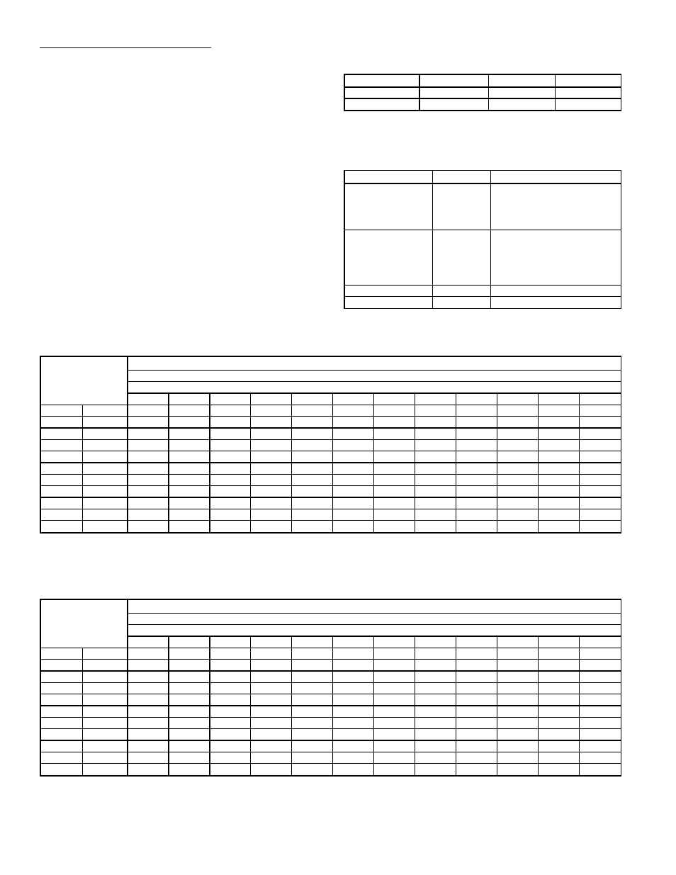
AC/HP CFM ADJUST (BLK) — The preset factory default
selection is MED. Selections HI and LO will adjust the air-
flow supplied for all operational modes (see following table).
The selection options allow installer to adjust airflow to meet
such individual needs as noise and static compensation, etc.
MODE
FAN ONLY
COOLING
HEATING
LO - Adjust
−15%
−10%
−10%
HI - Adjust
15%
10%
10%
AC/HP TIME DELAY (GRY) — Four motor operation delay
options are provided to customize system operation. See table
below:
OPTION
TERMINAL
DESCRIPTION
30-Sec On/60-Sec
Off Delay Profile
1
Used when it is desirable
to allow system coils time
to heat up or cool down
prior to airflow. Enhances
system efficiency.
No Delay Option
2
Preset factory default setting for
589A. Used for servicing or
when other components are
used to perform a delay func-
tion (e.g., integrated gas
control).
30-Sec Off Delay
3
Enhances system efficiency.
45-Sec Off Delay
4
Enhances system efficiency.
Table 8A — Superheat Charging Table, 588A018
TEMP (F)
OUTDOOR
ENTERING
AIR
INDOOR AIR — CFM
600
Indoor Air — Ewb (F)
54
56
58
60
62
64
66
68
70
72
74
76
65
SPH
17.3
18.5
19.6
20.8
24.2
27.7
28.5
29.3
29.3
29.3
29.3
29.3
70
SPH
13.8
14.9
16.1
17.3
20.7
24.1
25.7
27.3
27.3
27.3
27.3
27.3
75
SPH
10.2
11.4
12.5
13.7
17.1
20.6
22.9
25.2
25.2
25.2
25.2
25.2
80
SPH
8.2
8.8
9.5
10.2
13.6
17.0
20.1
23.1
23.9
24.1
25.4
26.1
85
SPH
6.1
6.2
6.5
6.6
10.0
13.5
17.3
21.1
22.6
24.1
25.6
27.1
90
SPH
*
*
*
5.0
8.1
11.4
15.2
19.0
20.5
22.0
23.5
25.0
95
SPH
*
*
*
*
6.2
9.4
13.2
17.0
18.5
20.0
21.5
23.0
100
SPH
*
*
*
*
*
7.3
11.1
14.9
17.2
19.5
21.7
24.0
105
SPH
*
*
*
*
*
5.3
9.1
12.9
15.9
18.9
21.9
24.9
110
SPH
*
*
*
*
*
*
6.7
10.8
13.8
16.8
19.8
22.8
115
SPH
*
*
*
*
*
*
*
8.8
11.8
14.8
17.8
20.8
LEGEND
Ewb — Entering Wet Bulb
SPH — Superheat at Compressor (F)
*Do not attempt to charge system under these conditions — refrigerant
slugging may occur.
Table 8B — Superheat Charging Table, 588A024
TEMP (F)
OUTDOOR
ENTERING
AIR
INDOOR AIR — CFM
800
Indoor Air — Ewb (F)
54
56
58
60
62
64
66
68
70
72
74
76
65
SPH
18.2
19.0
19.9
20.7
22.5
24.2
25.1
25.9
26.6
27.2
27.9
28.6
70
SPH
17.1
17.6
18.1
18.6
20.4
22.1
23.0
23.9
24.9
26.0
27.1
28.1
75
SPH
16.0
16.2
16.4
16.6
18.3
20.1
21.0
21.8
23.3
24.8
26.2
27.7
80
SPH
14.8
14.7
14.6
14.5
16.3
18.0
19.7
21.3
22.4
23.5
24.6
25.8
85
SPH
13.7
13.3
12.9
12.5
14.3
16.0
18.4
20.7
21.5
22.3
23.1
23.8
90
SPH
11.1
10.9
10.7
10.4
12.2
13.9
16.3
18.7
19.9
21.0
22.2
23.4
95
SPH
8.5
8.4
8.4
8.4
10.1
11.9
14.3
16.6
18.2
19.8
21.4
23.0
100
SPH
7.3
7.5
7.7
7.9
8.9
9.9
12.2
14.6
16.6
18.6
20.6
22.6
105
SPH
6.2
6.6
6.9
7.3
7.6
7.8
10.2
12.5
14.9
17.3
19.7
22.1
110
SPH
*
*
*
5.3
5.5
5.8
8.1
10.5
13.3
16.1
18.9
21.7
115
SPH
*
*
*
*
*
*
6.1
8.4
11.6
14.9
18.1
21.3
LEGEND
Ewb — Entering Wet Bulb
SPH — Superheat at Compressor (F)
*Do not attempt to charge system under these conditions — refrigerant
slugging may occur.
—36—