Maintenance – Briggs & Stratton FM3300 User Manual
Page 11
Part
No.
520141
Form
No.
F061604A
CABLE ADJUSTMENTS
17.1
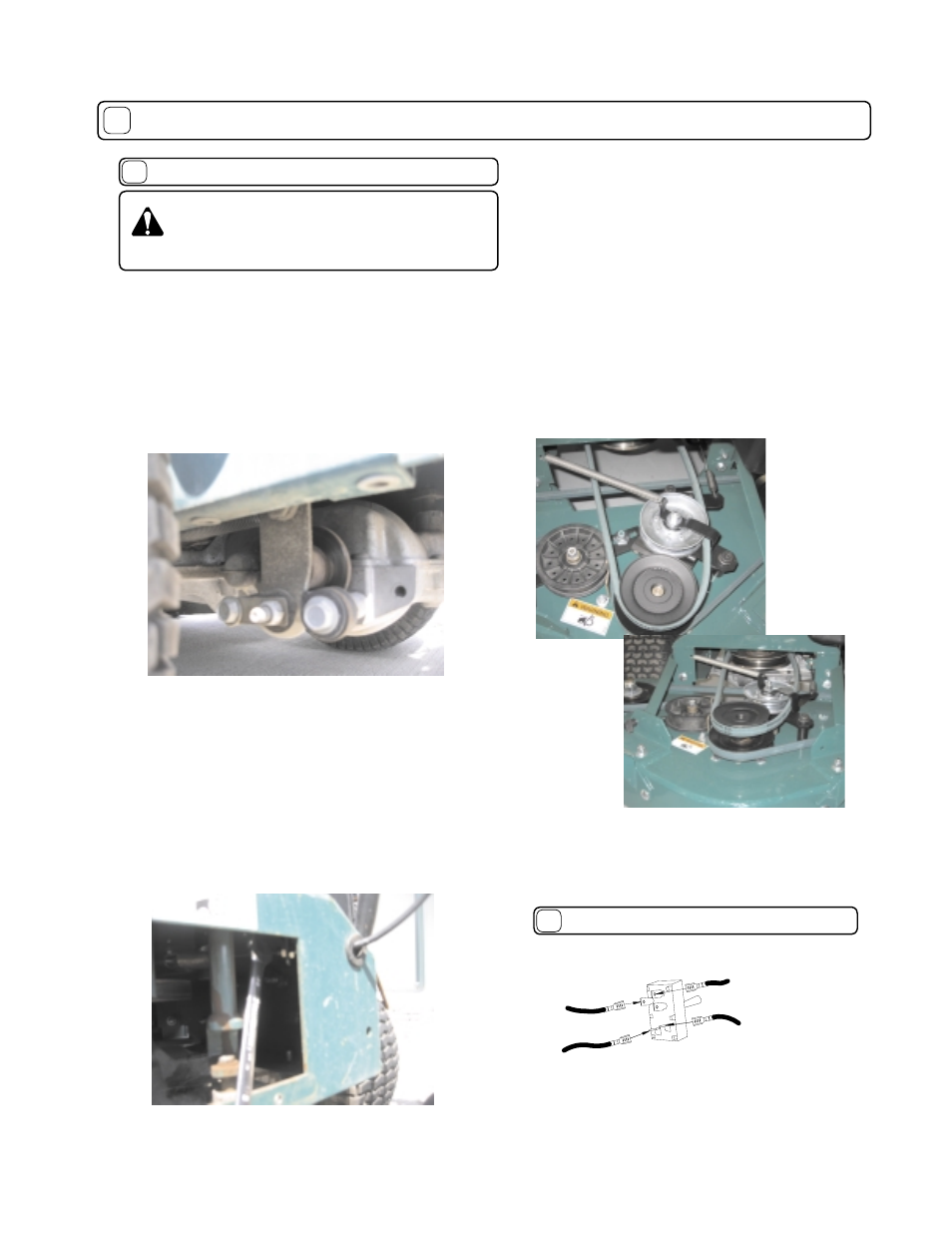
Brake Adjustment
The brake control cable is spring loaded and requires no adjustment; however,
the transaxle brake is adjustable. When the mower is in neutral and can
be pushed by hand without depressing the brake lever, the transaxle brake
needs adjustment.
Using a ½ inch wrench turn the adjusting nut ¼ turn clockwise (see fi gure
17-1).
With the machine in neutral and:
1. The brake lever not depressed, the brake should be on and inhibit the
machine from being rolled by pushing.
2. The brake lever depressed the brake should be off and the machine should
roll uninhibited by the brake.
Transaxle Drive Control Cable Adjustment
When the transaxle drive belt slips, the drive control cable needs to be
adjusted or the belt needs to be replaced with a new belt.
Cable Adjustment:
1. Using a 3/8” wrench, remove the rear access door (Item 51).
2. Using a ½ “ open end wrench, turn the inside adjusting screw clockwise
1/8 of a turn and then tighten the outboard adjusting nut against the support
bracket (see fi gure 17-2).
3. Check for proper operation. If the operation is not correct, repeat step 2.
4. Replace the access door.
The drive control cable adjustment should be the minimum amount required so
the belt does not slip when the drive is engaged.
CAUTION: DO NOT make cable adjustment
when engine is running. Disconnect spark plug
wire before making any adjustments.
Page 11 of 20
MAINTENANCE
continued
17
Blade Drive Control Cable Adjustment
When the blade drive control lever is depressed, the blades
should turn and the blade drive belt should not slip. When the
cable is properly adjusted the tension spring on the end of the
control cable will open slightly (only enough for a piece of paper
to slip between the coils). See fi gure 17-3.
Cable Adjustment:
1. Remove the deck belt cover (Item 81).
2. Observe the tension spring on the end of the cable when the
blade drive lever is depressed. The spring should just break open.
3. If adjustment is required, using a ½” open end wrench, turn the
inboard adjustment nut clockwise 1/8 of a turn (Figure 4). Then
tighten the outboard adjustment nut against the cable support
bracket (Item 49).
4. Check the spring tension with the blade drive lever depressed.
5. Readjust the control cable as needed for proper tension.
6. Replace the deck belt cover.
Note: Too much tension will shorten belt and bearing life and too
little tension will allow the belt to slip.
Figure 17-1
Figure 17-2
Figure 17-3
STARTER SWITCH WIRING
17.2
TO STOP SWITCH TERMINAL ON ENGINE
WHITE CONDUCTOR
TO GROUND
TO BATTERY (BATTERY TERMINAL ON BATTERY)
RED CONDUCTOR
GREEN/YELLOW CONDUCTOR
BLACK CONDUCTOR
TO STARTER SOLENOID