V9a series, Ratings & equipment listing – Burnham V9 User Manual
Page 4
1. Suffix “S” indicates steam boiler, “W” indicates water boiler. Suffix “G” indicates gas-fired, “O” indicates oil fired and “GO” indicates combination gas/oil fired.
2. Boiler ratings are based on 12.5% CO2 on oil; 9.7% CO2 on gas, and .10 in. water column pressure at boiler flue outlet.
3. I=B=R net ratings shown are based on piping and pick up allowances which vary from 1.333 to 1.289 for steam and 1.15 for water.
Consult manufacturer for installations having unusual piping and pick up requirements, such as intermittent system operation, extensive piping systems, etc.
4. The I=B=R burner capacity in GPH is based on oil having a heat value of 140,000 BTU per gallon.
Ratings shown above apply to altitudes up to 1000 feet on oil and 2000 feet on gas. For altitudes above those indicated, the ratings should be reduced at the rate of 4% for each
1000 feet above sea level.
Note:
Maximum allowable working pressure (MAWP):
Steam:
15 PSI
Water – USA:
80 PSI (standard relief valve provided is 50 PSI) (30 PSI and 80 PSI relief valve optional)
Water – Canada: 45 PSI (standard relief valve provided is 45 PSI) (30 PSI relief valve optional)
Form No. PL81401291000-4/13-2.5Mc Printed in the U.S.A.
V9A Series
RATINGS & EQUIPMENT LISTING
©2013 Burnham Commercial
•
P.O. Box 3939, Lancaster, PA 17604
Phone: 888.791.3790
•
www.burnhamcommercial.com
4
PA
G
E
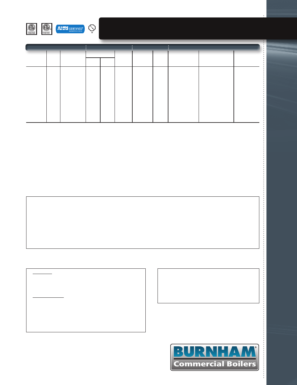
Boiler
Model (1)
Boiler
H.P.
Gross Output
MBH (2)
Steam
Water
MBH
Oil
(GPH) (4)
Gas
(MBH)
Net Firebox
Volume (Cu. Ft.)
Pressure in Firebox
(In. Wtr. Column)
I=B=R
Dia. (In.)
MBH Sq. Ft.
V903A
V904A
V905A
V906A
V907A
V908A
V909A
V910A
V911A
V912A
10.3
14.4
19.3
24.1
28.6
33.2
40.1
45.6
51.2
56.8
347
483
646
808
959
1,110
1,342
1,528
1,714
1,900
260
362
485
606
719
833
1,014
1,168
1,323
1,474
1,083
1,508
2,021
2,525
2,996
3,471
4,225
4,867
5,513
6,142
302
420
562
703
834
965
1,167
1,329
1,490
1,652
N/A
4.2
5.6
7.0
8.3
9.6
11.6
13.2
14.8
16.4
447
606
808
1,010
1,198
1,386
1,674
1,905
2,136
2,367
3.2
4.8
6.4
7.9
9.5
11.0
12.6
14.2
15.7
17.3
0.33
0.38
0.31
0.38
0.36
0.35
0.35
0.40
0.45
0.49
7
7
8
8
8
10
10
10
12
12
NET I=B=R RATING (2) (3) BURNER INPUT
PLEASE CONSULT BURNHAM COMMERCIAL WEBSITE FOR BOILER DIMENSIONAL DATA, PIPING CONFIGURATIONS AND BURNER MODELS/SPECIFICATIONS.
Standard Equipment
ALL BOILERS:
Sections unassembled, flush insulated jacket, burner mounting plate, burner adapter plate, rear flue outlet damper (top outlet optional), flue canopy,
rear observation port cover, target wall (V903A), and miscellaneous plugs, bushing and fittings, L4006B (low fire hold aquastat).
STEAM TRIM:
15 PSI safety valve, L404F pressuretrol, gauge glass assembly, steam gauge.
WATER TRIM:
50 PSI safety relief valve, L4006A high limit, pressure/temperature gauge.
OIL BOILERS:
Flange mounted flame retention oil burner furnished with two (2) stage fuel unit, primary control and dual oil valves.
GAS BOILERS:
Flange mounted gas burner with standard controls meeting the latest UL requirements, dual gas valves, gas-electric ignition with proven gas pilot, flame rod
on JR burner, ultra violet flame detector on others, electronic programming controls and components are factory wired in a burner mounted control panel.
GAS/OIL BURNERS: Flange mounted combination gas/oil burner with standard controls meeting latest UL requirements, manually operated fuel transfer switch for dual fuel
changeover, dual gas valves and oil valves, electric ignition with proven gas pilot on both fuels (direct spark ignition of oil is optional), ultra-violet flame
detector, electronic programming controls and components are factory wired in a burner mounted control panel.
Optional Equipment
Assembled sections; completely packaged (includes manual
reset high limit and manual reset low water cutoff); packaged
and fire-tested; top outlet flue damper; tankless heaters; side
inspection tappings with brass plugs; 30 PSI and 80 PSI safety
relief valves (water); combustion and hydronic controls to meet
special applications including F.M., I.R.I., and ASME CSD-1.
Optional Energy Management Interface
SBC Control
Maximizes system efficiency while providing peer-to-peer network,
burner modulation, boiler monitoring and diagnostic displays, outdoor air
reset, warm weather shutdown and domestic hot water priority features.
Universal Gateway
• Can be connected to a building’s Energy Management System
(EMS) using simple menu selections and wiring a 4-20mA input.
• Connects to EMS using modbus protocol
• Optional EMS Gateway to BacNet or LonWorks.
• Allows EMS controls to adjust either the SBC central heating
setpoint or the firing rate.