Ergo ii/mini arms/mini boards, Installation – Kuryakyn 4076 ERGO II/MINI ARMS with MINI BOARDS User Manual
Page 2
Use the supplied anti-seize for any chrome-to-chrome fasteners; this will prevent
galling and make future removal of fasteners easier.
INSTALLING CLAMP AND ARM
Mini Arms are suggested to be mounted above engine guard to avoid
a great reduction in cornering clearance. FIG 1
STEP 2
Locate the left (sitting on bike) mount; the mounts are side specific so be sure you
have the correct mount before attempting the installation. Visually inspect the
angle where the arm will be attached. The mount is angled slightly back, toward
the
rider,
NOT FORWARD. PIC 1
STEP 3
Remove the four 1/4”-20 fasteners securing the right mount together and
separate the upper and lower halves.
STEP 4
Insert the adjustable stop into the lower half of the mount. PIC 2 Thread two of
the included 3/8”-16 set screws into the bottom of the mount. Install the mount
onto the engine guard. Loosely secure the mount with the four 1/4”-20 fasteners.
Do not tighten at this time. PIC 3
STEP 5
Secure the Mini Arm to the cogged portion of the mount using one of the
1/2”-13 x 1-1/4” Button Socket Cap Screws and Wave washers (PIC 4) making
sure the cogs on the Mini Arm line up with the cogs on the mount. The Mini Arm
should be positioned level with or above the engine guard. FIG 1 Leave finger
tight
for
now.
STEP 6
Insert two roll pins into the holes in the clevis. PIC 5 Determine the desired
position of the foot peg using the positioning holes in the Mini Ergo Arm. PIC 5
FOOTRESTS MUST BE INSTALLED SO THEY WILL FOLD
UPWARD AND REARWARD IF HIT BY ANY OBJECT. FAILURE
TO ADJUST THE FOOTRESTS TO OPERATE IN THIS MANNER
COULD RESULT IN SERIOUS INJURY OR DEATH.
STEP 7
Insert the 1/2”-13 x 1-1/4” Socket Head Cap Screw through the back of the Mini
Arm and thread it into the clevis. Make sure the roll pins in the clevis line up with
holes on the Mini Arm. PIC 6 The roll pins will be pressed in as you tighten the
clevis. Leave finger tight for now.
STEP 8
Push down slightly on the Mini Arm and adjust the two setscrews below the
adjustable stop to fine tune the up and down angle of the mount and footrest.
PIC 3
STEP 9
Push down slightly on the Mini Arm (PIC 6) while tightening the four fasteners in
the bottom of the mount to take up any slack between the mount and the bottom
of the engine. Tighten securely.
STEP 10
Loosely install one of the Mini Boards into the clevis on the Mini Arm.
STEP 11
Repeat Steps 2
through
10
for
the
left
side.
STEP 12
Continue to the next
page
for
adjustment
and
tightening
procedures.
PAGE
2
ERGO II/MINI ARMS/MINI BOARDS
INSTALLATION
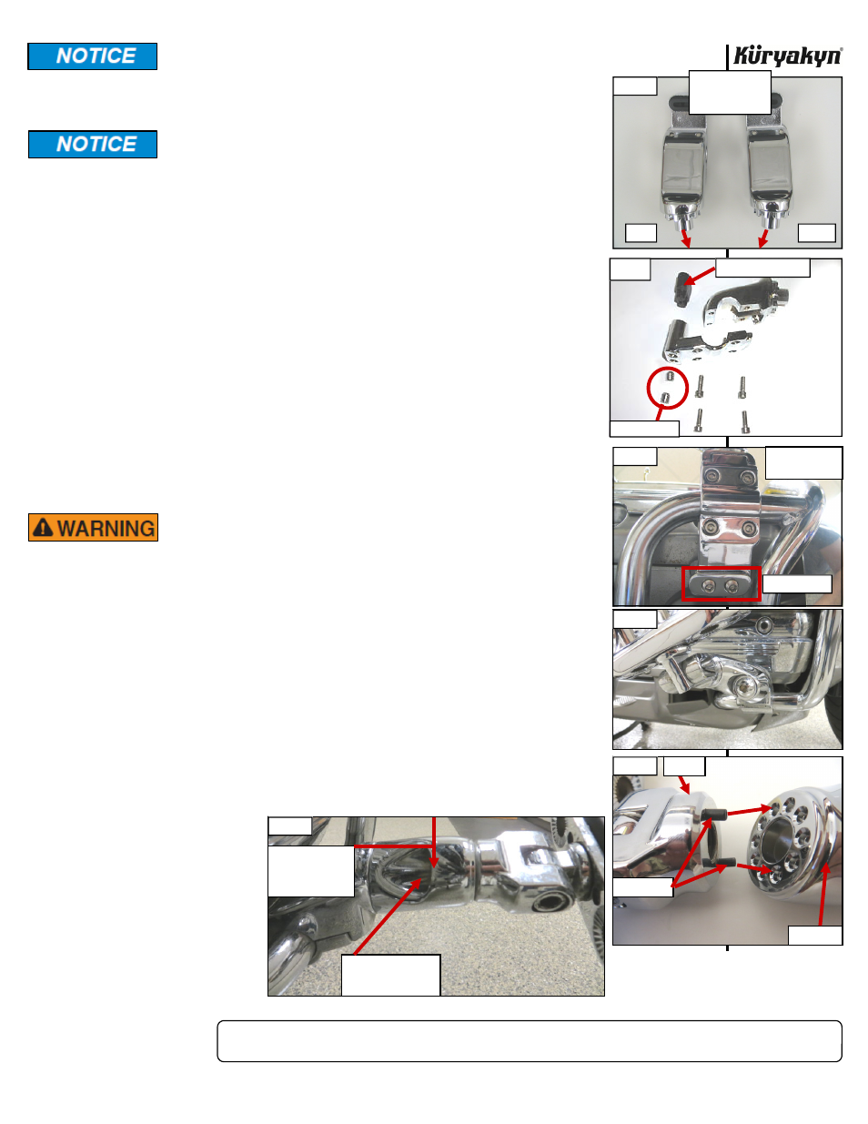
PIC 1
LEFT
RIGHT
ANGLE GOES
TOWARDS REAR
OF BIKE
PIC 3
SET SCREWS
VIEW FROM
UNDER MOTOR
-cont.-
PIC 4
PIC 2
SET SCREWS
ADJUSTABLE STOP
MINI ARM
ROLL PINS
CLEVIS
PIC 5
PIC 6
PUSH DOWN ON
MINI ARM WHEN
TIGHTENING THE
MOUNT
1/2” SOCKET HEAD
CAP SCREW GOES
HERE