Ergo iii adjustable cruise mount & clevis, Rotating arm assembly installation, Footpeg and clevis installation and adjustment – Kuryakyn 4080 ERGO III ADJUSTABLE CRUISE MOUNT & CLEVIS User Manual
Page 4: Installation
PAGE
4
ROTATING ARM ASSEMBLY INSTALLATION:
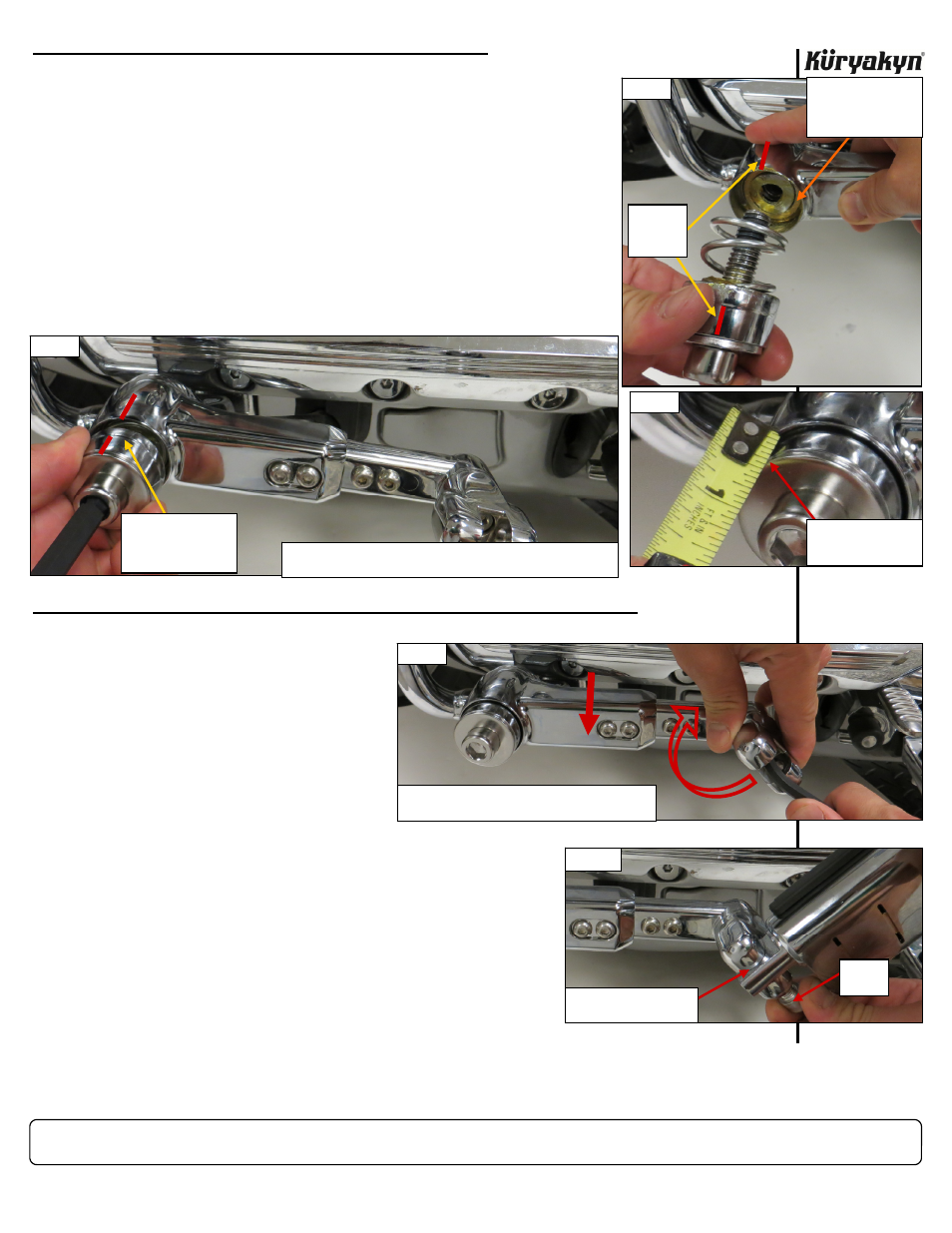
STEP 12
Position the Rotating Arm assembly (PIC 6 and 7) on the Ergo II mount
EXACTLY AS BEFORE in STEP 7. Ensure that the Arm is parallel to the
engine guard and valve cover.
STEP 13
Insert 1/2” Screw with the hardware (from STEP 11) through the Arm and
Helix. PIC 6 and 7 Torque the 1/2” Screw to 30 FT/LBS. Ensure the
marks (from STEP 6) stay aligned as you tighten the screw.
Step 14
Using a measuring tape or ruler, ensure that exactly 3/8” of the End Cap
protrudes from the assembly. PIC 8 Do not include the thickness of the
washer. If necessary, loosen the 1/2” Screw and “re-seat” the End Cap as
you re-tighten the screw. This will ensure that the End Cap is properly
aligned with the nose of the Helix.
FOOTPEG AND CLEVIS INSTALLATION AND ADJUSTMENT:
STEP 15
Refer to PIC 9. Remove the clevis-
mounting screw and apply some Blue
Loctite (248) to the threads. Reinstall
the screw. Push down on the Rotating
Arm until it reaches its stop; adjust the angle of the clevis so the
footpeg will fold up and back at an angle. Ensure the splines on
the clevis and arm engage and tighten the clevis-mounting screw.
Torque the screw to 20 FT/LBS.
Step 16
Apply some Blue Loctite (248) to the clevis screw threads. Install
the clutch-side footpeg in the clevis and secure it with the clevis
screw. PIC 10 If necessary, use the included Wave Washers to
take up any excess space between the footpeg adapter and the
clevis. Torque the screw to 25 FT/LBS.
STEP 17
Loosen the footpeg screw to adjust the footpeg angle. Tighten the
footpeg screw.
STEP 18
Repeat
STEPS 3 through 17 for the right side.
ERGO III ADJUSTABLE CRUISE MOUNT & CLEVIS
INSTALLATION
NOTE:
Place a drop of Loctite Thread-
locker Blue 248 on the threads of
the clevis and footpeg screws
before installing. Follow the
manufacturer’s recommendations
for proper application.
PIC 7
ENSURE THE ROTATING ARM IS AT LEAST PARALLEL WITH THE
ENGINE GUARD AND VALVE COVER
ENSURE MARKS STAY
ALIGNED AS YOU
TIGHTEN THE 1/2”
SCREW
PIC 6
ADD A DAB OF
GREASE TO KEEP THE
BUSHINGS IN THE
ARM
MARKS
FROM
STEP 6
ENSURE 3/8” OF END
CAP PROTRUDES
FROM ARM ASSEMBLY
PIC 8
-cont.-
PIC 9
PUSH DOWN ON THE ARM AND ADJUST THE CLEVIS
SO THE FOOTPEG WILL FOLD UP AND BACK.
PIC 10
USE A WAVE WASHER TO
TAKE UP EXCESS SPACE
CLEVIS
SCREW