Ab c, Extension arm and clevis installation – Kuryakyn 4082 ERGO III ADJUSTABLE CRUISE MOUNTS WITH PREMIUM MINI BOARDS User Manual
Page 3
PAGE
3
STEP 7
Refer to PIC 8. Position the clutch-side upper clamp-half
(separated in STEP 3) over the engine guard and align it
with the bottom clamp-half. Secure the bottom to the top
with the four screws removed in STEP 3. PIC 8
NOTE:
Do not fully tighten the screws at this time.
Leave them snug to allow for adjustment of the
mounts.
STEP 8
Repeat
STEPS 2 through 7 for the other side.
EXTENSION ARM AND CLEVIS INSTALLATION:
STEP 9
Locate one of the Extension Arms in the Hardware Kit. The Arms are NOT side specific.
STEP 10
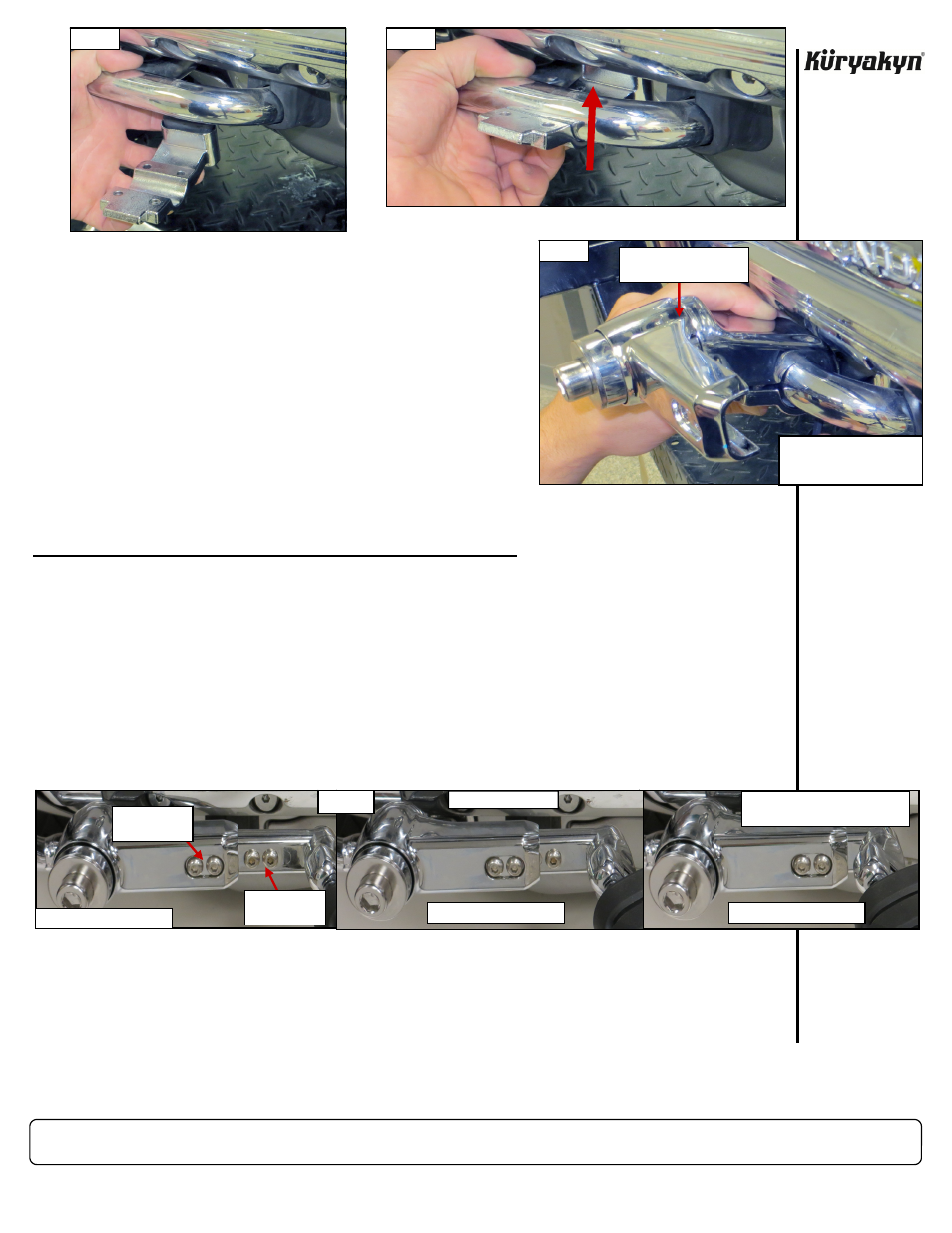
Refer to PIC 9 below. The Extension Arms allow for three possible foot positions.
A
shows a possi-
ble Extension Arm position for riders with shorter legs.
B
shows the position for riders with me-
dium length legs.
C
shows the position for riders with longer legs. Determine which Extension Arm
position will suit you best.
STEP 11
On the clutch-side of the bike, attach the Extension Arm to the Rotating Arm with two of the in-
cluded 1/4”-20 X 1-1/8” Button Socket Head Screws. Thread the screws through the Extension
Arm and secure them on the back side with two of the included Nylock Nuts. Fill any exposed
threaded holes with the included 1/4”-20 X 5/16” Button Socket Head Screws. PIC 9
A
Torque
the screws to 10 FT/LBS.
ERGO III ADJUSTABLE CRUISE MOUNTS WITH MINI BOARDS
INSTALLATION
PIC 6
PIC 7
PIC 8
UPPER CLAMP-HALF AND
ARM ASSEMBLY
SECURE THE BOTTOM
CLAMP TO THE TOP WITH
THE FOUR SCREWS
-cont.-
SHORTER LEG POSITION
MEDIUM LEG POSITION
LONGER LEG POSITION
PIC 9
A
B
C
1/4-20 X 1-
1/8 SCREWS
1/4-20 X 5/16
SCREWS
CLUTCH-SIDE (LEFT)
EACH POSITION IS APPROXI-
MATELY 1/2” APART