Multi-rack, Installation – Kuryakyn 7159 MULTI-RACK User Manual
Page 2
STEP 2
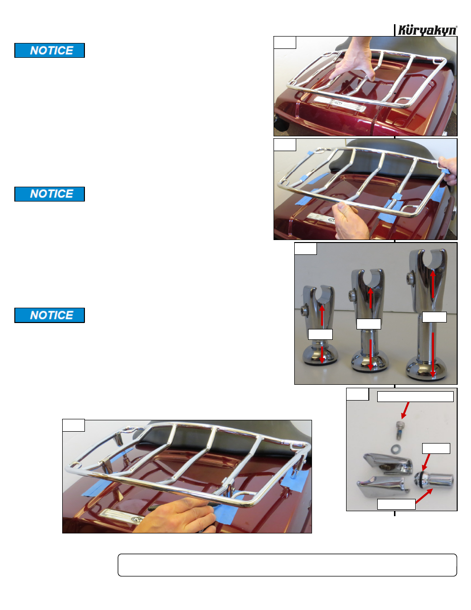
Determine the best mounting location of the Multi-Rack by holding it above the trunk lid. PIC 1
Each mounting foot requires at least a 1 1/8 inch
diameter FLAT area to mount.
DO NOT mount all four feet on the center two
bars.
It is highly recommended that the clamp/stand
assemblies be positioned as far apart front to
back as possible.
DO NOT attach the clamp assemblies on a bend in
the rack bars.
STEP 3
Mark the locations for the clamp on the rack with masking tape
or non-permanent marker. Mark the locations of the feet on the
lid with masking tape. PIC 2
STEP 4
Determine the best combination of mounting legs.
Short, Medium and Tall mounting legs have been
included to accommodate different shaped trunk
lids. PIC 3
It is recommended to mount the rack as horizon-
tally as possible. Select the combination of mount-
ing legs that will allow for the most horizontal
position.
STEP 5
To allow for adjustment, loosely assemble the clamp/stand assemblies
at the marks on the rack. Loosen the socket head cap screw in the
clamp assemblies until they are able to be slipped over the rack bars.
Snug the fasteners to allow adjustment of the clamps on the rack
bars.
Tightening the socket head cap screw in the clamp as-
sembly will simultaneously secure the clamp to the bar
and the mounting leg. PIC 4 Ensure that the mounting
legs remain in the clamps when attaching to the rack
bars.
Ensure that the o-rings remain installed on the mount-
ing leg ball end. PIC 4
STEP 6
Gently rest the rack on top of the tape marks on the lid to confirm the
fitment of the mounting locations. PIC 5 Make any necessary adjust-
ments to the clamp/stand assemblies. Slightly loosen the clamps to avoid scratching
the rack bars. See NOTICE on the next page.
MULTI-RACK
INSTALLATION
PAGE
2
PIC 1
PIC 2
PIC 3
2 3/4”
2 1/4””
1 3/4”
PIC 5
PIC 4
O-RING
SOCKET HEAD CAP SCREW
MOUNT LEG
-cont.-