Standard chrome hypercharger — bolt, Installation – Kuryakyn 9426 STANDARD CHROME HYPERCHARGER — BOLT User Manual
Page 2
STEP 1
Read and understand all steps in the instructions before start-
ing the installation. Park the motorcycle on a hard, level sur-
face and turn off the ignition. Allow the engine and exhaust
system to cool.
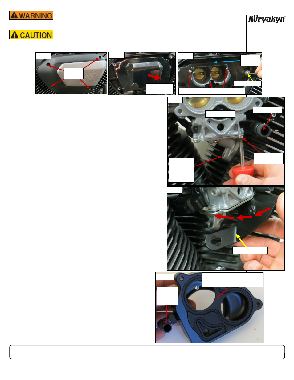
STEP 2
Refer to PIC 1 through 3. Remove existing air cleaner cover,
filter element, and backing plate; save the three screws
shown in PIC 3.
STEP 3
Refer
to
PIC 4. Disconnect the breather hose from the back-
side of the backing plate. Ensure the spring clip remains on
the hose; it will be reused. Set the backing plate aside, it will
not be reused.
STEP 4
Refer
to
PIC 4. Remove the lower screw from the timing
chain tensioner housing. Set the screw aside; it will not be
reused.
STEP 5
Refer
to
PIC 4. Remove the front Phillips head screw from
the bottom of the throttle body. Set the screw aside; it will
not be reused.
STEP 6
Locate the included Mounting Bracket. Secure the Mounting
Bracket to the underside of the throttle body with an included
M5 X 0.8 X 14MM Socket Head Cap Screw and M5 Split Lock
Washer. Leave the Screw finger tight for now.
NOTE:
Remove one Phillips head screw at a time
to prevent dislodging the plate and O-ring
it secures.
STEP 7
Remove the rear screw from the underside of the throttle
body. Refer to PIC 5. Swing the Mounting Bracket in until the
holes align; secure the Bracket with the other M5 Screw
and Lock Washer. Leave the Screw snug for now.
STEP 8
Align the Mounting Bracket slot with the hole in the
timing chain tensioner housing; thread the included M6
Socket Head Cap Screw with Flat Washer through the
slot and into the tensioner housing. Leave the Screw
snug for now.
STEP 9
Tighten the two M5 Screws from
STEP 6 and 7
. Do
NOT over tighten the Screws. Tighten the M6 Screw
from
STEP 8
.
STANDARD CHROME HYPERCHARGER — BOLT
-cont.-
INSTALLATION
Working around the sharp edges of the cylinder-head fins exposes
your hands to injury. Wear protective gloves to prevent serious
injury.
YOU WILL BE WORKING AROUND THE ENGINE AND EXHAUST
SYSTEM DURING INSTALLATION. ENSURE THAT THE ENGINE AND
EXHAUST SYSTEM HAVE FULLY COOLED TO PREVENT INJURY.
PAGE
2
THROTTLE BODY
REMOVE THE
FRONT SCREW
REMOVE THE
LOWER
SCREW FROM
TIMING CHAIN
TENSIONER
HOUSING
PIC 4
BREATHER HOSE
PIC 6
90 DEGREE
FITTING
POINTS
INWARD
INSTALL RUBBER INLET FLOW PLATE
IN BACKSIDE OF ADAPTER. ENSURE
PLATE FULLY SEATS IN RECESS
PIC 5
MOUNTING BRACKET
PIC 2
REMOVE
SCREWS
REMOVE FILTER
ELEMENT
PIC 1
REMOVE
SCREWS
PIC 3
REMOVE AND SAVE THESE THREE SCREWS
BACKING
PLATE
REMOVE SCREW