Ride on, Black kinetic floorboard inserts with toe rests, Installation – Kuryakyn 7619 BLACK KINETIC FLOORBOARD INSERTS WITH TOE RESTS User Manual
Page 2
PAGE
2
STEP 3
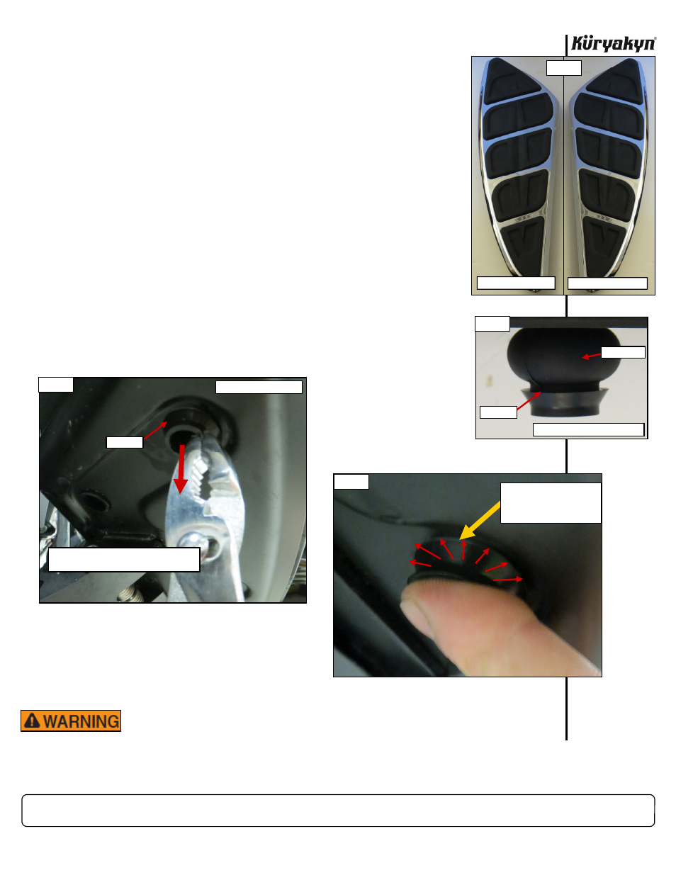
Determine the clutch-side (left) Kinetic floorboard insert from the brake-side (right). PIC 2
NOTE:
It may be helpful to lubricate the flanges on the isolators
(PIC 3) with warm soapy water to ease installation.
STEP 4
Position the left-side Kinetic floorboard insert over the four holes in the board.
Align the four rubber isolators with the holes in the board. PIC 3
STEP 5
Gently pull on the isolators until the flanges are all the way through the holes.
PIC 3 and 4
STEP 6
Ensure that the flanges have been pulled completely through the holes. PIC 5
The flanges secure the floorboard insert to the board.
STEP 7
Repeat
STEPS 3 through 6
for the brake side (right).
NOTE:
If used, the warm soapy water should be rinsed out and al-
lowed to dry completely before operating the bike.
NOTE:
Ensure that there is sufficient clearance between the shift
peg and the top surface of the floorboard. Refer to the service
manual for specific shift lever adjustment procedures. Also,
check for proper brake pedal clearance BEFORE riding.
BLACK KINETIC FLOORBOARD INSERTS WITH TOE RESTS
INSTALLATION
Ride On!
CLUTCH-SIDE (LEFT)
BRAKE-SIDE (RIGHT)
PIC 2
PREVENT LOSS OF CONTROL. ENSURE THAT THE FLOORBOARD
INSERTS DO NOT INTERFERE WITH THE PROPER OPERATION OF
THE SHIFTER OR BRAKE PEDAL. LOSS OF CONTROL CAN RESULT
IN SERIOUS INJURY OR DEATH.
PIC 5
ENSURE THE FLANGE HAS
BEEN PULLED COMPLETELY
THROUGH THE HOLE
PIC 4
GENTLY PULL ON THE ISOLATORS UNTIL
THE FLANGES ARE THROUGH THE HOLES
FLANGE
UNDERSIDE OF BOARD
PIC 3
FLANGE
ISOLATOR
UNDERSIDE OF FLOORBOARD