Velociraptor air cleaner – Kuryakyn 9443 VELOCIRAPTOR AIR CLEANER User Manual
Page 2
INSTALLATION
VELOCIRAPTOR AIR CLEANER
STEP 3
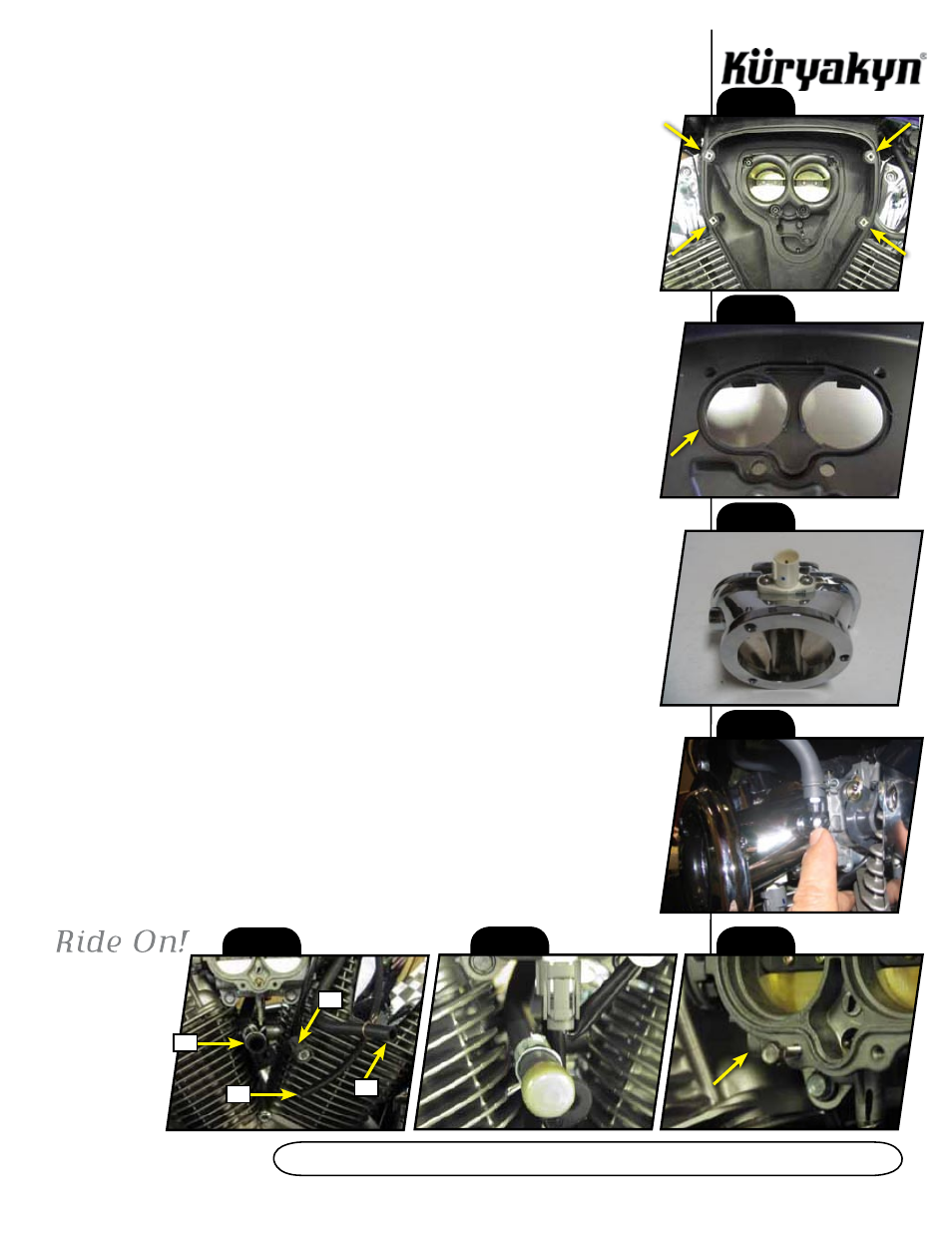
Either prop the rear of the tank up, or have an assistant hold the rear of the tank up.
Remove the four Phillips head screws form the “air horn” assembly in the stock air cleaner backing
plate. (See PIC.1.) Gently “tug” outward at the bottom of the stock air cleaner back and it will
become free from the bike, only to be connected by hoses and a wire harness. Remove the three
hoses from the backing plate as well as the plug from the air mass (temp) sensor.
The stock backing plate may now be removed from the motorcycle, and the tank may now be
returned to its original position and re-connected and seat reinstalled. The stock backing plate will be
able to be removed by holding up on the back side of the fuel tank, but it will be a tight fit.
STEP 4
See PIC.2, and PIC.3. Remove the white plastic air mass (temp) sensor and the
O-ring from the stock backing plate. Install the O-ring into corresponding groove in the
new cast throttle body adapter. Install the air mass sensor into the adapter at this time
using the 10 x 24 B.S.C.H. Install the chrome elbow into the manifold then the nipple
into the elbow. Make sure to point the nipple up. Your crank case ventilation hose should
be rerouted over the top of the throttle body so it can be plugged into this nipple. See
PIC.4.
STEP 5
See PIC.5. The largest diameter hose (marked as A) will be capped offusing the vinyl cap
(PIC.6) included in the kit. The intermediate size hose (marked as B, about 3/8” I.D.) will be plugged
into the nipple you have installed on the throttle body adaptor (this is your crankcase breather). The
smallest hose (marked as C) is the vacuum line that was plugged into the top of the stock air box.
This hose can be shortened but must be plugged with the 1” pin supplied. The air mass sensor plug
(marked as D is also shown in PIC.5).
STEP 6
This step will require some patience as you will be working in a very limited space. See
PIC.7. Start one of the M5 hex flange bolts in one of the two lower mounting holes of the throttle
body. Slide a corresponding slot on the throttle body adapter on to this bolt. Start the remaining
three bolts in the adapter mounting holes. Screw the BOTTOM two mounting screws in
all the way - it may be easier for you to hold the adapter out away from the throttle body as you
run these screws in. You will most likely have to use your open-end wrench and move the fasteners
about 1/6 of a turn at a time. Once the bottom two screws are in all the way, but not tightened,
you may thread the top two mounting screws in. Tighten all four screws, but do not over tighten - if
you snap or strip one of these screws, you will have to repeat this process. Reconnect the plug to
the air mass sensor that was disconnected in STEP 3.
STEP 7
Fasten the supplied adhesive gasket to the intake manifold.
STEP 8
Locate the velocity stack (chrome cone) from the Velociraptor Assembly. Line the holes
up from the velocity stack through the manifold. Secure using the 3 1/4-20 x 1/2" Socket Head
Cap Screws.
STEP 9
Place the plastic cone inside the velocity stack, replace the filter element and secure with
the outer trim ring and mesh screen.
STEP 10
Check all hose connections and tighten all hardware.
ATTENTION!
It is the installer’s responsibility to ensure that all of the fasteners (including pre-
assembled) are tightened before operation of the motorcycle. Küryakyn will not warranty
components lost due to improper installation. Periodic maintenance may be required.
PIC. 1
PIC. 2
PIC. 3
PIC. 4
PIC. 5
A
C
D
B
PIC. 6
PIC. 7