Led windshield trim for fltr — black, Remove the outer fairing, Install the turn signal wiring adapters – Kuryakyn 1339 LED WINDSHIELD TRIM FOR FLTR — BLACK User Manual
Page 2: Installation
REMOVE THE OUTER FAIRING:
STEP 2
Remove the screws and washers securing the windshield to the fairing; set the screws
and windshield aside for now. One screw and all five washers will be reused.
STEP 3
Remove the rubber well-nuts and rubber washers from the fairing; set them aside, they
will be re-used.
STEP 4
Remove the acorn nuts and flat washers securing the turn signal assemblies to the fair-
ing; set the nuts and washers aside they will be re-used later. Pull the turn signal assem-
blies away from the fairing. Older models require removal of a stud plate from the inner
fairing support.
NOTE:
Secure the turn signal assemblies to the engine guard with zip ties
or masking tape to keep them from falling once the fairing is re-
moved.
STEP 5
Refer
to
PIC 1. Remove the Torx screws (
1
) and (
2
) from both sides; set them aside
they will be re-used later. Note that the lower screws (
1
) are long and the middle screws
(
2
) are short.
NOTE:
Assistance is recommended when removing the
outer fairing to minimize the possibility of dam-
age.
STEP 6
Refer
to
PIC 1. Remove the upper Torx screws (
3
) from both sides;
set them aside for now.
STEP 7
Lift up on the front of the fairing to disengage it from the bike.
STEP 8
Squeeze the two tabs on one of the headlight connectors and CARE-
FULLY disconnect it from the bulb. Repeat for the other bulb.
STEP 9
Remove the outer fairing from the bike; set it on a soft blanket on a
sturdy surface.
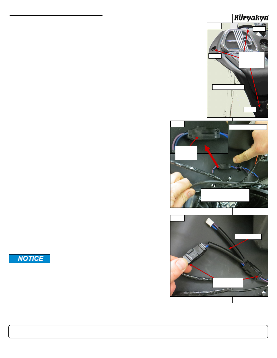
INSTALL THE TURN SIGNAL WIRING ADAPTERS:
STEP 10
Refer
to
PIC 2. Disconnect the OEM turn signal connectors.
NOTE:
‘98-’03 MODELS: have a 6-pin connector located
on the clutch-side (left) of the fairing. The black
6-pin connector is usually taped to a wiring har-
ness. Disconnect the 6-pin connector.
STEP 11
Locate the included “Y” connectors. Apply some of the included di-
electric grease to the open ends of ALL the connectors.
STEP 12
Refer
to
PIC 3. Connect the “Y” connectors to the turn signal con-
nectors.
NOTE:
‘98-’03 MODELS: locate the included 6-pin adapter; apply dielectric grease to
the open ends, then connect the it inline with the OEM turn signal wiring.
LED WINDSHIELD TRIM FOR FLTR — BLACK
-cont.-
INSTALLATION
Kuryakyn recommends the use of the included
dielectric grease on ALL electrical connections.
PAGE
2
PIC 1
REMOVE THE
UPPER, MIDDLE,
AND LOWER
TORX SCREWS
1
2
CLUTCH-SIDE (LEFT)
SHORT
LONG
3
SHORT
PIC 3
“Y” CONNECTOR
OEM TURN SIGNAL
CONNECTORS
PIC 2
LOCATE THE TURN SIGNAL
CONNECTORS ON THE INSIDE
OF THE INNER FAIRING
2004-UP MODEL SHOWN
OEM TURN
SIGNAL
CONNECTOR