Driver/passenger backrest, Installation – Kuryakyn 1661 MULTI-PURPOSE DRIVER/PASSENGER BACKREST User Manual
Page 2
PAGE
2
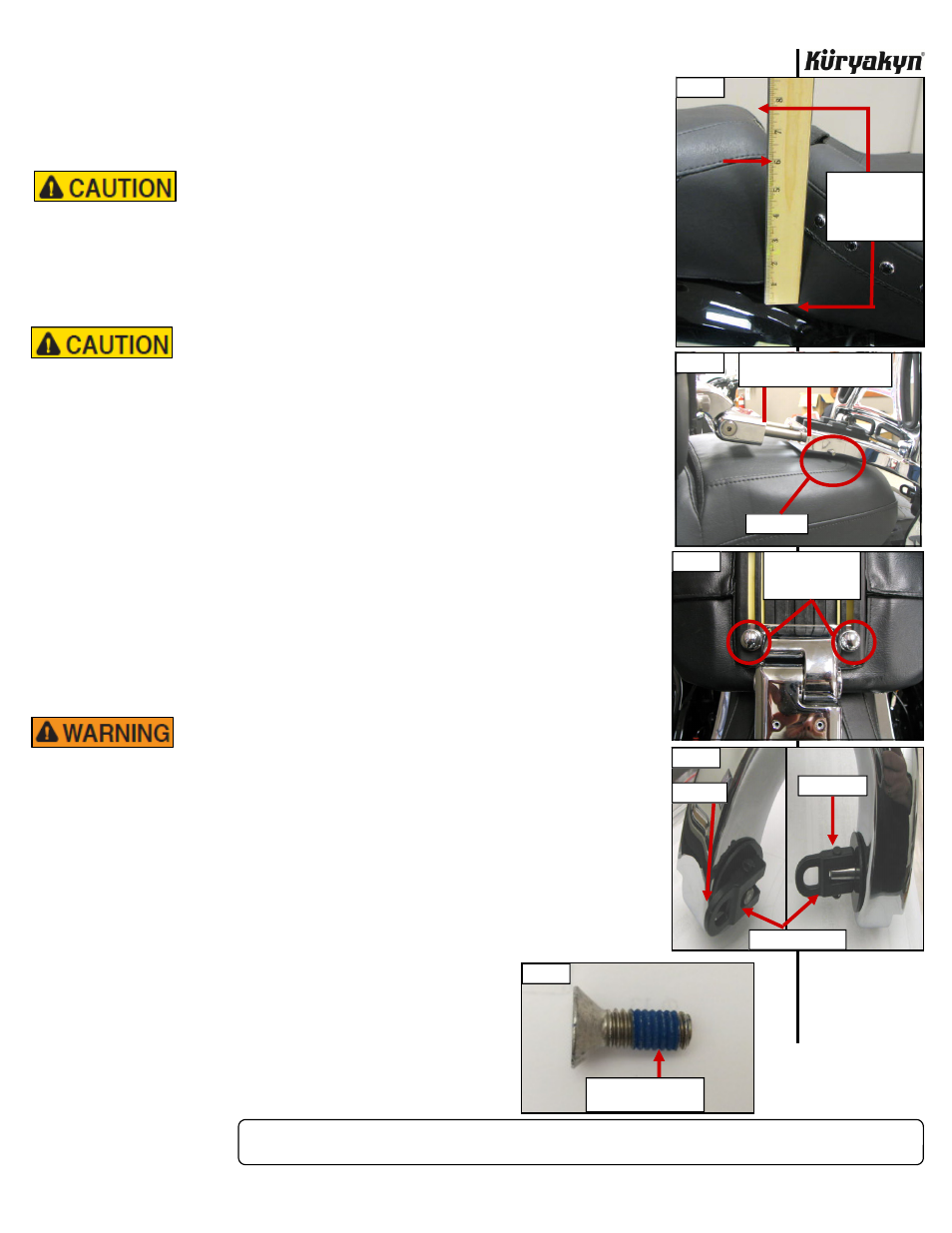
NOTE:
Due to the great variety of seats available,
to
determine the correct mount height
needed, measure the thickness of the front of the passenger seat. Measure
from the top of the rear fender to the top of the passenger seat as in
PIC 1. Over 6 inches need the tall mounts, 6 inches and under will use the
short
mounts.
Avoid potential pinch or crush injuries! Only perform the
following procedure with the backrest in the lowered (driver)
position.
STEP 2
To adjust the Backrest further forward for the driver, depress the lock pin on the
side and pull the pad to the desired position. Make sure when the pad is in the
desired
position,
the
lock
pin is fully extended. PIC 2
DO NOT extend or retract the Backrest in the upright
position! Keep fingers away from the area between the pad
mount and the backrest when retracting the pad assembly.
The weight of the Backrest could quickly retract it causing
injury.
STEP 3
To adjust the Backrest pad up or down once it is in the desired upright or forward
position, loosen the two Knurled/Slotted screws and slide the pad up or down to
the desired position. When the pad is in the desired position, tighten the
Knurled/Slotted screws securely. PIC 3
STEP 4
To raise the backrest to the passenger position or lower it to the driver position:
fold the locking levers to the straight out position and lower or raise the backrest
to the desired location. PIC 4 Fold the locking levers over to lock them in place.
Gently move the Backrest up and down to ensure the locking pins are engaged in
the slots in the Fixed Mounts. Visually inspect the Shoulder Washers and
Countersunk Socket Head Cap Screws at the pivot point for any signs of
loosening before each ride. Küryakyn requires checking all backrest
attaching fasteners to the torque specifications defined in these
instructions every 3,000 to 5,000 miles.
BOTH PIVOT/HINGE SCREWS MUST HAVE THREADLOCK
COMPOUND RE-APPLIED AND RE TORQUED ONCE REMOVED
AFTER INITIAL INSTALLATION. FAILURE TO DO SO MAY
RESULT IN UNINTENDED LOOSENING AND MAY CAUSE
SERIOUS INJURY OR DEATH. THE FEMALE THREADS IN THE
MULTI-PURPOSE BACKREST AND THE THREADS ON THE
REMOVED SCREWS WILL NEED TO BE CLEANED TO REMOVE
ANY THREADLOCKER RESIDUE BEFORE RE-INSERTING.
RE-APPLY LOCTITE® THREADLOCKER BLUE 242® OR
EQUIVALENT, AS SHOWN IN PIC 5, RE-TORQUING TO
15 FT-LBS (20.3 NM) USING A TORQUE WRENCH AND 3/16”
ALLEN/HEX KEY ATTACHMENT. LET CURE PER THE
THREADLOCK MANUFACTURERS INSTRUCTIONS AFTER
INSTALLATION. IF YOU DO NOT WISH TO
APPLY THREADLOCKER, THEN ORDER A
NEW SERVICE KIT, (P/N 991660) WHICH
WILL CONTAIN SCREWS WITH BLUE
THREADLOCK ADHESIVE PRE-APPLIED.
DRIVER/PASSENGER BACKREST
INSTALLATION
PIC 1
MEASURE FROM
THE TOP OF
FENDER TO TOP
OF PASSENGER
SEAT
PIC 3
LOOSEN THESE
TO ADJUST PAD
UP OR DOWN
PIC 2
LOCK PIN
KEEP FINGERS OUT OF THIS
AREA WHEN ADJUSTING
PIC 4
UNLOCKED
LOCKED
LOCKING LEVERS
PIC 5
APPLY TREADLOCKER
TO SCREW
-cont.-