Warning, Fuse replacement cleaning replacement parts, Analog model remote intensity control – Dolan-Jenner A242 User Manual
Page 3: Performance statement
WARNING
Replace the fuse with the correctly
rated fuse as listed on the label
on the back of the illuminator. Use of
an improper fuse can create
a hazardous situation.
FUSE REPLACEMENT
CLEANING
REPLACEMENT PARTS
!
!
!
!
!
!
!
Press the ON(1)/OFF(0) switch to the OFF(0) position.
Remove the AC line cord from the AC power receptacle.
Remove the AC line cord from the power entry module at the rear of the illuminator. The fuse drawer is part of the power
entry module. The drawer is located directly beneath where the AC line cord plugs in.
Pull out the fuse drawer. Remove the blown fuse. The second fuse is the spare.
Place the replacement fuse into the fuse drawer. The fuse will work in either orientation.
Push the fuse drawer until it "clicks" into position.
Attach the AC line cord to power entry module at the rear of the illuminator. The illuminator is now ready for service
If necessary wipe exterior surfaces only with a soft cloth. Do not use fluids to clean the exterior of the illuminator. Under no
circumstances allow fluids of any kind to enter the illuminator power supply or lamp module(s).
686009-02787
A241P
Fuse, 3.15A, 5 x 20, 250 V, slow blow
686009-02786
A242P
Fuse, 6.3A, 5 x 20, 250 V, slow blow
.
Part No.
Model
Description
ANALOG MODEL REMOTE INTENSITY CONTROL
(Models A241PA and A242PA)
The Remote Intensity Control is located on Pin 3 of the Remote Interface.
When the PANEL/REMOTE switch is in the REMOTE position the intensity
is controlled by the signal applied to Pin 3. The input signal must be limited
to a 0 to +5 volt DC signal. A negative voltage or a voltage in excess of 5
volts will cause the lamp to run at maximum intensity potentially shortening
lamp life. The A-241P/A-242P Remote Intensity control is highly linear. At 0
volts the lamp voltage is 0 volts. At +5 volts the lamp voltage is the maximum
voltage for the lamp specified at the time the order was placed. A 2.5 volt
input signal will cause the lamp to run at 50% of lamp voltage. Refer to Table
A for intermediate values.
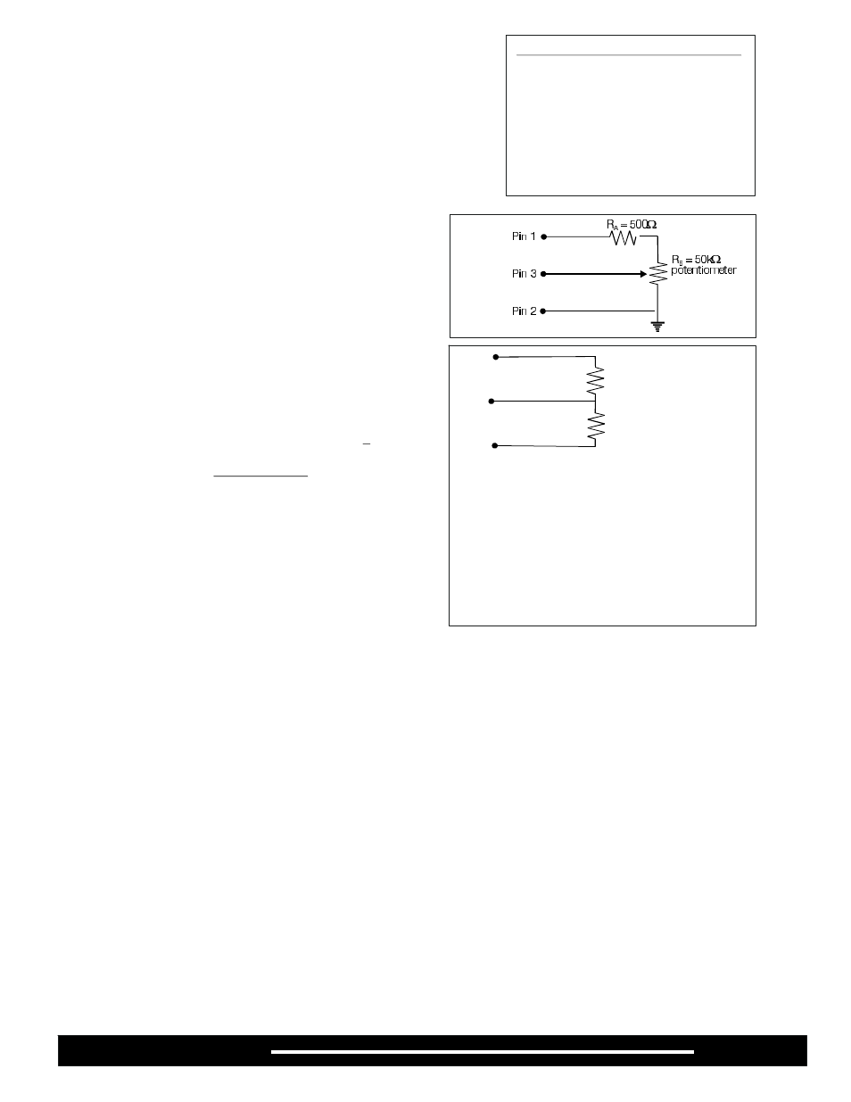
Pin 1 can be used to supply power to a remote potentiometer.
Connect the potentiometer as shown in Figure A. The 500 ohm
series resistor prevents shorting the power supply on Pin 1 if the
potentiometer should fail as a short circuit. In all cases the
minimum resistance between Pin 1 and common ground (Pins 2
and 15) must be at least 500 ohms to prevent damage to the Pin 1
power supply.
The user may also use a fixed voltage divider to control the
illuminator at a non-varying intensity level. Refer to Figure B and
the resistance values in Table 1 for sample resistor values and the
corresponding lamp intensity levels. In all cases, the minimum
total resistance value connected between Pin 1 and common
ground (Pins 2 and 15) must be 500 ohms (RA + RB
500 ohms.)
>
Analog Remote Control - Pin Assignments
Pin # - Signal
1
+5 VDC at 10mA max.
3
0 - 5 V (+) input
2, 15 0 - 5 V (-) input (common return)
14
Remote On/Off Open
16
Chassis ground (shield)
17
Lamp Fail
4-13
Open
18-25
Open
Pin 1
Pin 3
Pin 2
R
A
R
B
RA ( )
RB ( )
Voltage VDC
% @ Full Intensity
(Pin 3)
Ω
Ω
20K
5.0
100%
20K
2.2K
4.5
90%
20K
5K
4.0
80%
20K
8.6K
3.5
70%
20K
13K
3.0
60%
20K
20K
2.5
50%
13K
20K
2.0
40%
8.6K
20K
1.5
30%
PERFORMANCE STATEMENT
Dolan-Jenner Industries, Inc. (DJI) recognizes that its illuminator products may be used under an almost unlimited variety of conditions.
As such, we are prepared to assist the customer in the selection and application of any of these products. This includes application engineering,
sample testing and other means as determined by DJI.
Where DJI has made specific recommendations for its products, systems, or detection techniques (based on complete and detailed
information furnished by the customer) we will extend every effort to assure that the customer is satisfied with the performance of our products.
Continual development and improvement of DJI products may require changes in details that do not coincide with descriptions or illustrations
shown. All fiber optic bundle diameters are nominal.
Page 3
A241P / A242P