Dolan-Jenner A242 User Manual
Page 2
DIGITAL MODEL REMOTE INTENSITY CONTROL
PROGRAMMING THE
REMOTE DIGITAL
INTERFACE
Intensity Level / Digital Code
RESPONSE TIME
The Digital Remote Intensity Control uses an 8 bit, latching, parallel input Digital to Analog converter. The Digital Remote
Intensity Control is
Centronics parallel compatible. Refer to the pinout below.
Establish the digital control
code onto pins DB0(LSB) to
DB7(MSB).
Pull the Input Enable pin 10
Low to load the code into the
remote interface.
Pull the Input Enable pin 10
High to latch the code into the
remote interface. The digital
code will remain loaded until a
new code is provided and the Input Enable signal is toggled.
Intensity
Binary Code
Hex Code
21.0 volts (full power)
11111111
FFh
10.5 volts (approx. 1/2 power)
10000000
80h
0 volts (min. power)
00000000
00h
A one(1) bit change in the digital code is equivalent approximately to 82 millivolts. The digital code to lamp voltage is linear over
the 0 to 255 range of inputs.
The Remote Control module will respond to the change in digital input within several milliseconds of the Input Enable falling
edge. However, due to the thermal inertia of the lamp, the illumination level of the lamp may take several hundred milliseconds to
several seconds to respond depending on the magnitude of the intensity change. The response time is also a function of the
individual lamp characteristics and may change from lamp to lamp.
NOT
REMOTE ON/OFF FUNCTION
The Remote On/Off function will operate with the Panel/Remote switch in both the
Panel and Remote positions. Connect a +5v signal to pin 14 to inhibit power to the
lamp. The fan will still operate.
Remove the +5v signal from pin 24 (pin 14 on Analog models) to enable power to
the lamp. The +5v on pin 1 can be used for this function. Use a manual switch. relay
or FET switch to connect and remove the 5v signal on pin 24 (pin 14 on Analog
models).
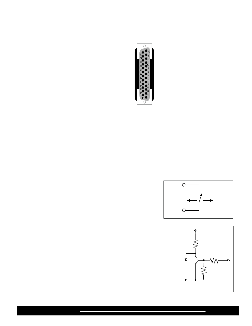
Digital Remote Control - Pin Assignments
PIN
DESCRIPTION
PIN
DESCRIPTION
1
+5v 10 mA max.
10
Input Enable(CE)
2
DB0 (LSB)
11-22
Common Ground
3
DB1
23
Lamp Fail
4
DB2
24
Remote On/Off
5
DB3
25
Open
6
DB4
7
DB5
8
DB6
9
DB7 (MSB)
Pin 1
+5v
Lamp
Power Off
Pin 24
Pin 14 on Analog models
Lamp
Power On
LAMP FAIL SIGNAL
A signal indicating that the lamp has failed is available on Pin 23 (pin 17 on Analog
models). This signal is open collector (see Figure IV). The user must supply the
necessary circuitry to connect the lamp out signal to a signaling device. The
maximum current through the circuit is 10 mA. When the signal at Pin
is logic High(5v) the lamp has failed.
The Lamp Fail signal will detect if current has stopped flowing to the lamp while the
intensity control signal is not at 0 volts, the illuminator On-Off switch is in the On
position and the Remote On-Off signal is in the On condition. The Lamp Fail signal
will also indicate if the lamp is not properly seated after a lamp change or if the
lamp power connector is not properly connected after a lamp change or if the lamp
socket was replaced.
23 (pin 17 on
Analog models)
47
W
PIN 23 (17 Analog)
10K
Lamp Fail Ckt.
Page 2
A241P / A242P