Control Company 6580 MAXITHERMAL ELECTRONIC DATA LOGGER User Manual
Page 2
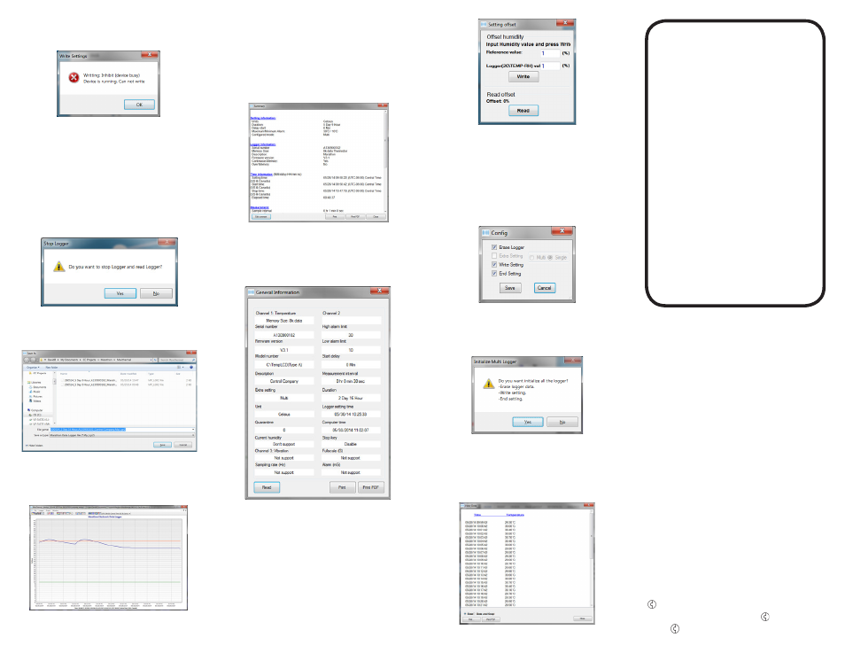
• Data-Logger shall be in Stop state to upload all setting.
If the Data-Logger is still in use, the software will prompt
an error message, see Fig. 8.
FIGURE 8
2.1.14. Erase all data
• Erase all user setting from the Data-Logger’s internal
memory, and ready for next initialization
• If necessary, download all recorded data from the
Data-Logger before erasing all data. All recorded data
will be lost once Erase all data operation is complete
2.1.15. Event log
• Display software status
2.2. Read Logger
2.2.1. If the Data-Logger is still in use, the software will
display a warning message, see Fig. 9
FIGURE 9
2.2.2. Click Yes to read data from the Data-Logger, and
software prompts to input filename and location, see
Fig. 10.
FIGURE 10
2.2.3. Click No, Data-Logger will continue to record, and
data will not be downloaded to computer
2.2.4. Once data is downloaded to computer, data graph will
be displayed, see Fig. 11
FIGURE 11
2.3. Stop C\TempLCD(Type A)
2.3.1. Stop Data-Logger from recording data. The software
will ask for confirmation before stopping Data-Logger
2.3.2. If Stop Key is set to No, Data-Logger can only be
stopped from logging data through MaxiThermal
software via USB connection
2.4. Summary
2.4.1. Displays summary of opened records, see Fig. 12
FIGURE 12
2.5. General Information
2.5.1. Retrieve and display information on Data-Logger’s
device information and settings.
2.5.2. Click Read to retrieve information from Data-Logger.
Note: Data-Logger must be stopped to read. See Fig. 13
FIGURE 13
2.6. Multi Traces
2.6.1. Display multiple traces at the same graph.
2.6.2. Click Open to open multiple traces. Maximum number
of traces is 20.
2.7. Setting Offset humidity–Only available Logger-Trac™
TEMP-RH
2.7.1. Setting offset, see Fig. 14
FIGURE 14
2.7.2. Input Reference value and Logger value, and click
Write
2.7.3. Click Read to read offset value
2.8. Multi Logger Initialization
2.8.1. Initialize multiple Data-Loggers simultaneously
2.8.2. Set the parameters as stated in 2.1
2.8.3. Click Config Initialization, and a new window pops up,
see Fig. 15
FIGURE 15
2.8.4. Click Write To All Device to perform operations speci-
fied in 2.8.3. A confirmation window pops up, see Fig.
16. Click Yes to start initialize multiple loggers, or click
No to return.
FIGURE 16
2.9. Calib Buzz – not available
3.
Graph
3.1. View Summary Information: refer to 2.4
3.2. View Data
3.2.1. View recorded data only, see Fig. 17
FIGURE 17
3.2.2. Check Data or Data and Graph to print data only or
data with graph.
3.3. Copy to clipboard
3.3.1. Copy the graph to clipboard so that it can be pasted
3.4. Edit
3.4.1. Edit the displayed graph: title, trace color
3.5. Grid
3.5.1. Turn on/off vertical grid, horizontal grid
3.6. Toolbar
3.6.1. Toggle toolbar display
4.
Window
4.1. When multiple recorded data files are open, select the
way they are displayed
4.2. Fullscreen all: full screen display. Click opened file to
switch displayed graph
4.3. Cascade all: cascade all opened graph
WARRANTY, SERVICE, OR CALIBRATION
For warranty, service, or calibration contact:
CONTROL COMPANY
4455 Rex Road
Friendswood, Texas 77546 USA
Ph. 281 482-1714 • Fax 281 482-9448
www.control3.com • [email protected]
Control Company is ISO 9001 Quality-Certified by DNV and ISO
17025 accredited as a Calibration Laboratory by A2LA
Control Company Cat. No. 6580
Traceable
®
is a registered trademark of
Control Company.
©
2014
Control Company.
92-6580-00 Rev. 0 061914
™
MAXITHERMAL
SOFTWARE
FOR
ELECTRONIC
DATA LOGGER
INSTRUCTIONS