BRK electronic 4120B User Manual
Page 15
13
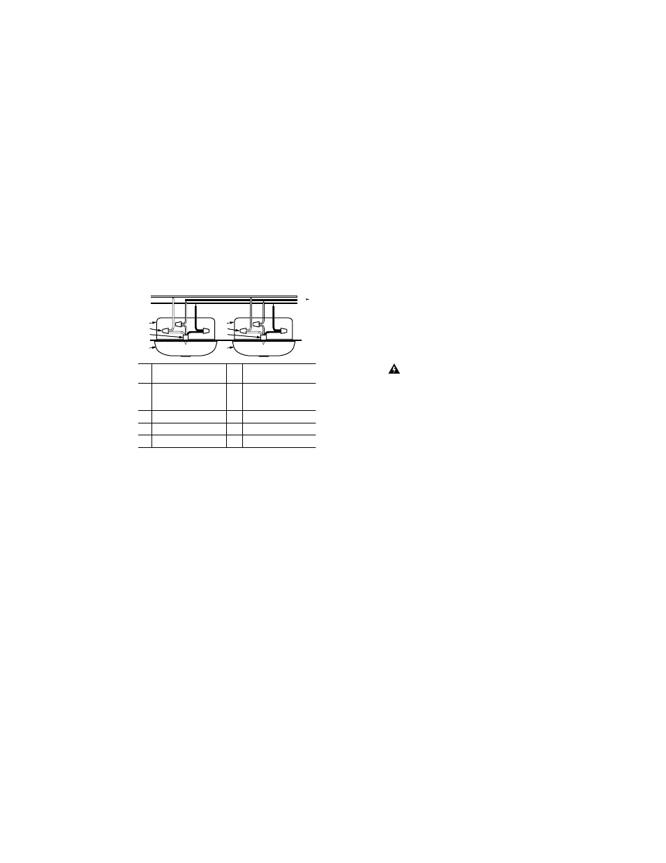
Interconnecting Multiple Smoke Alarms
To install and interconnect multiple alarms:
1. Remove mounting bracket from the base.
Position screw slots on mounting bracket over
screws in the junction box. Tighten screws.
2. Strip off about 1/2” (12 mm) of the plastic coating
on the orange wire on the power connector.
3. Using wire nuts, connect the power connector to
the household wiring.
•
Connect the white wire on the power connector
to the neutral wire in the junction box.
•
Connect the black wire on the power connector
to the hot wire in the junction box.
•
Connect the orange wire on the power connec-
tor to the interconnect wire in the junction box.
Repeat for each unit you are interconnecting.
Never connect the hot or neutral wires in the
junction box to the orange interconnect wire.
4. Plug the power connector into the back of the
smoke alarm.
5. Position the base of the alarm over the mounting
bracket and turn. The alarm can be positioned
over the bracket every 60°. Turn the unit
clockwise (right) until the unit is in place.
DANGER
!
ELECTRICAL SHOCK HAZARD. Do not restore
power until all smoke alarms are completely
installed. Restoring power before installation is
complete may result in serious electrical shock,
injury or death.
6. Make sure each unit is receiving AC power.
Under normal operation, the green power
indicator light will shine continuously.
7. Test each smoke alarm. Press and hold the test
button until the unit alarms.
When testing a series of interconnected units
you must test each unit individually. Make sure
all units alarm when each one is tested.
NOTE: When power is applied, unit(s) may alarm
momentarily.
IMPORTANT!
If any unit in the series does not alarm,
TURN OFF
POWER
and recheck connections. If it does not
alarm when you restore power, replace it immediately.
;;
;;
;;
;;
;;
;;
;;
;;
;;
;;
;;
;;
;;
;;
;;
;;
;;
;;
;;
;;
;;
;;
6
7
8
4
3
1
5
4
3
1
5
2
A
B
}
}
;;;;;;;;;;;;;;;;;;;;;;;;;;;;;;;
;;;;;;;;;;;;;;;;;;;;;;;;;;;;;;;
A
Unswitched 120V AC
60Hz source
4
Wire nut
B
To additional units
Maximum = 18 (Max.
12 smoke alarms)
5
Junction box
1
Smoke alarm
6
Neutral (white) AC wire
2
Ceiling or wall
7
Interconnect wire
3
Power connector
8
Hot (black) AC wire