Installation diagram, Wire size and fuse ratings, Dimension drawings – Blue Sea Systems 7650003 Add-A-Battery Kit - 120A [Boxed] User Manual
Page 2: Engines with combined alternator and starter wires, Engines with separate alternator and starter wires
990310020 Rev. 007
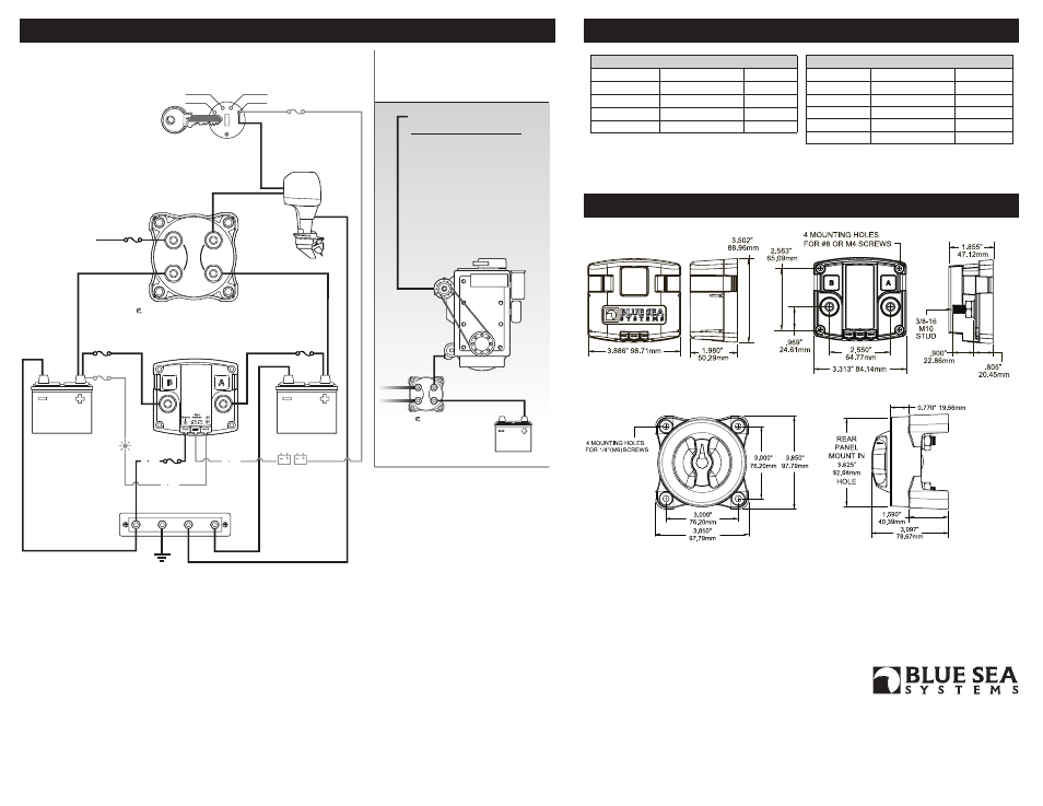
Wire Size and Fuse Rating Chart (Metric)
Charging Amps Minimum Wire Size*
Fuse Rating
≤50
10 mm²
75-80A
≤70
16 mm²
80-90A
≤90
25 mm²
125-130A
≤110
35 mm²
150A
≤120
50 mm²
150-175A
Wire Size and Fuse Rating Chart (AWG)
Charging Amps Minimum Wire Size* Fuse Rating
≤60
#6
75-90A
≤80
#4
100-125A
≤100
#2
150A
≤120
#1
175A
* Larger wire sizes may be required to minimize voltage drop in long wire runs.
For more information, please visit the Circuit Wizard at circuitwizard.bluesea.com
Installation Diagram
Wire Size and Fuse Ratings
Dimension Drawings
start
engine
accessory
off
to
house
loads
2
1
e
-Series Dual Circuit Plus™ battery switch
Start
Battery
House
Battery
10 AMP
FUSE
16 AWG
COMMON BUS BAR
16 AWG
16 AWG
GROUND
START KEY SWITCH
2AMP
FUSE
OPTIONAL
REMOTE
LED
OPTIONAL
START ISOLATION
(SI) WIRE
GROUND
ENGINES WITH ALTERNATOR AND
STARTER WIRES COMBINED
(Typical of Outboard Motors)
See Wire Size and Fuse Rating charts for connections from Terminals A and B.
Note: To determine wire sizes and fuse ratings for all other wires illustrated
please visit the Circuit Wizard at circuitwizard.bluesea.com
ALTERNATOR
STARTER
2
1
e
-Series
Dual Circuit Plus™ battery switch
2A FUSE
Engines With Combined Alternator and Starter Wires
- typical of outboard motors
Start
Battery
Alternator Wiring may
Include the Following:
1. to Starter
2. to Engine terminal of
battery switch
3. to Start Battery
4. to House Battery
Alternator connected to a larger
battery bank is most efficient.
This diagram is for reference only.
Alternator wiring configuration does
not affect ACR installation.
Engines With Separate
Alternator and Starter Wires
- typical of inboard engines
SI-ACR
AUTOMATIC
CHARGING
RELAY
with
START
ISOLATION
* These installation diagrams show typical applications only. Your application may differ.
For further information, please go to www.bluesea.com and navigate to
Resources/Application Briefs and Technical Briefs.
* Because the SI-ACR is Dual Sensing, terminals A and B are interchangeable.
ACR function will not be affected by reversal of the starting and house batteries versus
the diagram.
* If the COMBINED indicator LED is flashing, the ACR is in a lockout state, and will
not combine batteries until the lockout condition is removed. Ensure neither battery is
below 9.5V for a 12V system or 19V for a 24V system. Also ensure positive voltage
is not present on the Start Isolation terminal.
* It is recommended that the ACR be connected directly to your battery positive terminals
through appropriately sized fuses. Connecting in a different location such as a battery
switch may affect accuracy because of voltage drop along current carrying conductors.
* If you are not knowledgeable about electrical systems, please consult an electrical
professional for help with installation.
425 Sequoia Drive
Bellingham, WA 98226 USA
p 360.738.8230
p 800.222.7617 USA and Canada
f 360.734.4195
www.bluesea.com