Sd meter1-2 eng (parts list-installation).pdf, Parts list, Installation – BLITZ SD Meters User Manual
Page 2: Meter holder installation
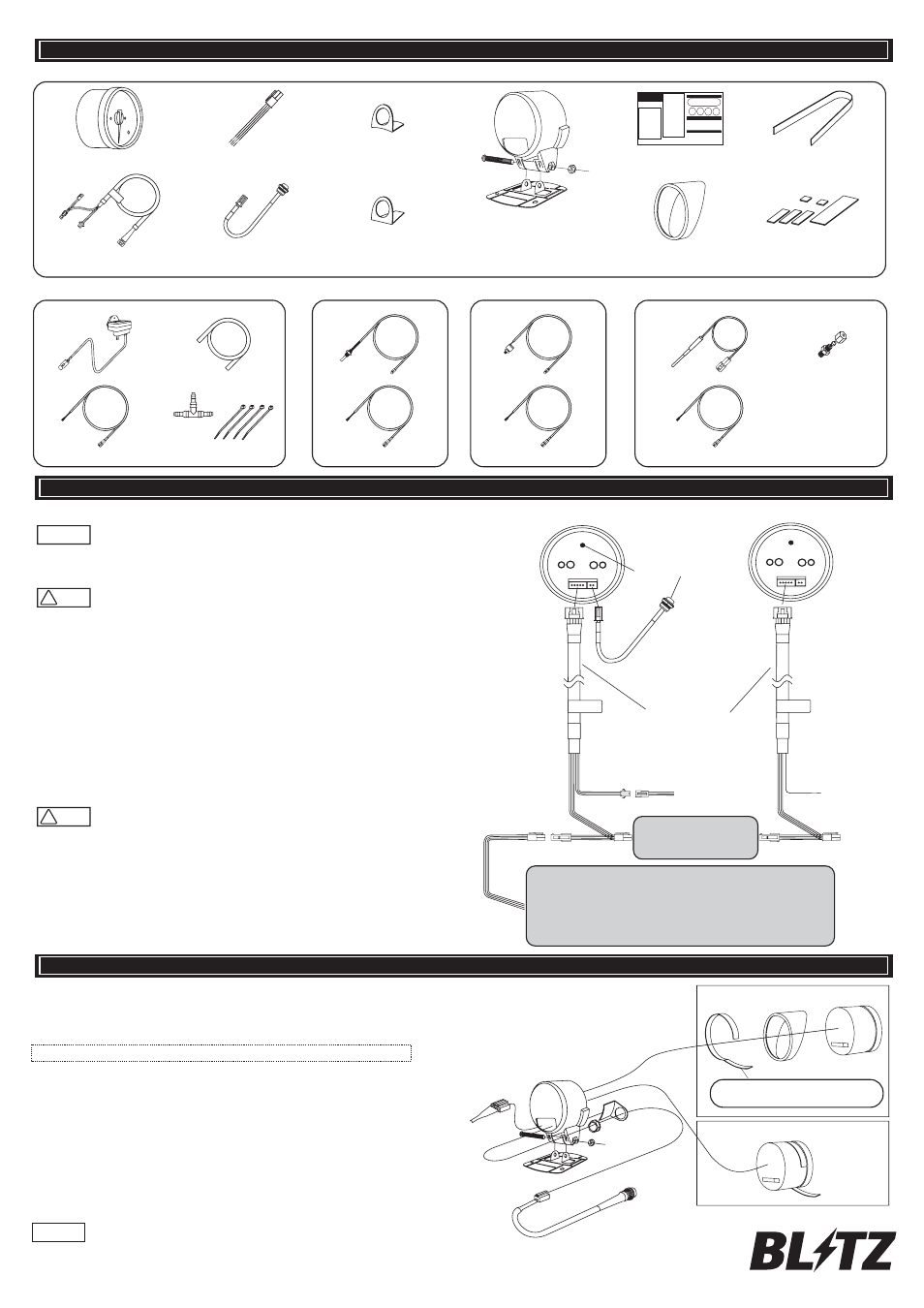
PARTS LIST
Meter Unit ×1
Power harness(50cm) ×1
Switch mount ×1
(For meter case)
Meter holder×1
Bolt ×1
Nut ×1
Mount base ×1
Main harness(1m)※ ×1
External control switch(20cm) ×1
Switch mount ×1
(Universal)
Instruction Manual ×1
Meter visor ×1
Sponge tape(16cm) ×1
Double-sided adhesive tape
Large, medium, small total 6
※ The appearance is different
for TACHO(RPM), VOLT.
□Common parts
□Product-specific parts
Boost sensor(20cm) ×1
Sensor harness(2m) ×1
Vacuum hose×1
(φ4 20cm)
3-way joint ×1
Zip-ties ×4
BOOST/VACUUM
TEMP sensor (40cm) ×1
Sensor harness (3.5m) ×1
TEMP
PRESS sensor(30cm) ×1
Sensor harness (3m) ×1
PRESS
EX.TEMP sensor (30cm) ×1
Sensor harness (2m) ×1
Sensor fitting ×1
EX.TEMP
INSTALLATION
① Disconnet the negative (-) terminal of the battery.
Connect the power harness as illustrated on the right side.
②
Install each sensors, referring to “Sensor Installation” on the back side of this instruction,
※In case of TACHO (RPM), connect the wiring to to RPM signal line from ECU.
Wiring diagram is available at BLITZ homepage.
(http://www.blitz.co.jp/Operation-manual/Operation-manual.htm)
Separate sensor wiring is not required for VOLT meter.
③
Connect main harness with meter unit, sensor harness, power harness (not needed for additional unit),
and external control switch. From the second meter, connect the main harness to the
split of the previous main harness for the power suppy.
④
Re-connect the negative (-) terminal of the battery.
⑤
Make sure to disengage the latch of the connector when disconnecting.
Pulling on the wires can cause damage to the wire and/or damage to the product.
Note that shape/location of the latch can vary depending on the connector.
CAUTION
!
Connect the wiring with solder, connector or electrical tap. Make sure to insulate the
connected area to avoid the shortcircuit. If the wiring requires protection,
use protection tube from the retail stores.
CAUTION
!
Equipments such as radio can lose memory when the battery is disconnected.
Please take the setting note, and reprogram the equipment after the installation is complete.
Attention
Meter unit (Back)
TACHO(RPM)
Meter holder installation
Insert the mounting base into the meter holder, and fix with bolt and nut.
Insert switch bracket
①
Attach a sponge tape on the meter unit. Be careful not to wrinkle the sponge tape.
When attaching the meter visor, attach metervisor before attaching the sponge tape.
②
Remove the nut behind the external control switch, and place the switch through the bracket,
and fix with the nut again.
③
Connect the main harness and external control switch on the back of the meter, through
the meter holder.
④
Inset the meter unit into the meter holder. Be careful with the sponge tape from detaching.
⑤
Place double-sided adhesive tape to the mount base.
Before attaching the meter onto the mounting surface, bend the mount base to fit the mounting surface.
Attach the adhesive tape with various sizes sor maximum adhesion surface area.
⑥
Clean and degrease the mounting surface, and attach the mounting base with double-sided adhesive tape.
If the double-sided tape is not secure enough, use tapping screw (Not included) for reinforcement.
⑦
Fo the maximum adhesion of the double-sided adhesive tape,
make sure to clean/degrease the mounting surface thoroughly.
Be careful not to damage the wiring by pinch the wires
in between the meter unit and the meter holder.
□
□
Attention
Attach meter visor before attaching
the sponge tape.
Without meter visor
With meter visor
Red (+B):
To battery(+); Constant 12V power
Orange(IGN): To power line with IGN ON
Yellow (ILM): To illumination power line
Black (GND):
To battery (-); GND
※Back light dimmer activates with 12V input)
Control Switch
External
Control Switch
Main Harness
To sensor
From the 2nd meter and after,
connect to previous main harness
for power supply
Power Harness
To ECU signal line
(RPM/TACH)
Function of the control switch on the back of the meter can be replaced
by connecting external control switch to the meter.
※
All warning/peak memory of other SD meter will be cleard
if the first power harness is disconnected,
in case that power supply is shared with first SD meter.
※
Note: Meter visor and switch bracket cannot be used at the same time.
※