Installation instructions – BLACKHAWK! POWERPAK MODULAR CHEEK PIECE User Manual
Page 2
Page 1
Page 2
www.BLACKHAWK.com
©BLACKHAWK! Products Group
™
NORFOLK, VA U.S.A. 1.800.694.5263
www.BLACKHAWK.com
©BLACKHAWK! Products Group
™
NORFOLK, VA U.S.A. 1.800.694.5263
Installation Instructions
Installation Instructions
1. If the desired configuration involves the use of the High Cheek Piece proceed to
Step 2. If the desired configuration involves only the use of the Low Cheek Piece
proceed to Step 4.
2. Utilizing the High Cheek Piece requires the use of the Low Cheek Piece. With
the two long flat edges facing down, place the Low Cheek Piece on a level work
surface. Note: The PowerPak Logo should be readable and not upside down.
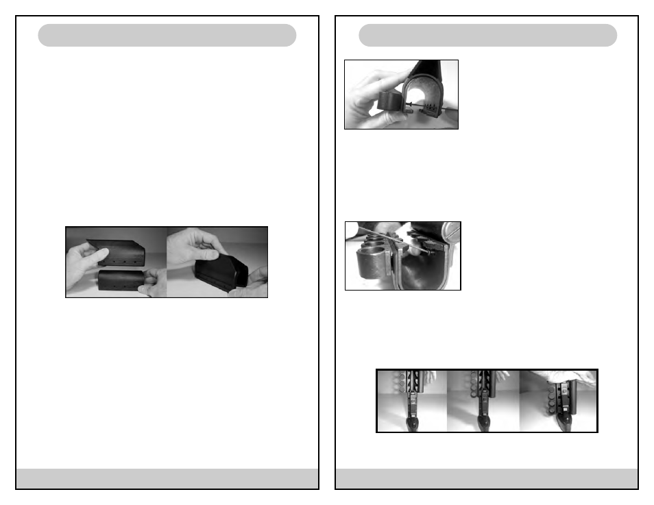
3. Take the High Cheek Piece in one hand while holding the Low Cheek Piece in a
steady position. Slide the High Cheek Piece down over the top of the Low Cheek
Piece (See Fig. 1). Note: Logo on high cheek piece should align with the logo on
low cheek piece. The High Cheek Piece should lock down and completely cover
the Low Cheek Piece. The rear portion of the High Cheek Piece should be flush
with the rear portion of the Low Cheek Piece.
If the desired configuration does not involve the use of the Shell Holder or
Battery/Storage Compartment proceed to Step 10.
4. If the desired configuration involves the use of both the Shell Holder and
Battery/Storage Compartment it easier to install the Shell Holder first. Installation
of the Shell Holder requires the use of the 4 Long Screws (1/2” OAL) and the Ball
End Wrench. Right hand shooters should install the shell holder on the right side
of the stock.
5. Align the holes in Shell Holder with the holes in the side of cheek piece(s). The
rear of the cheek piece is indicated by the PowerPak logo. The front of the Shell
Holder can be determined by the forward facing arrow molded on the inside.
6. With the Shell Holder properly aligned with the cheek piece, insert the Ball End
Wrench through the holes on the opposite side of the cheek piece (See Fig.2).
Position screw in first hole and begin threading. Hand tighten screw until snug.
Repeat for all 4 screws. If the desired configuration does not involve the use of
the Battery/Storage Compartment proceed to Step 10.
7. Installation of the Battery & Storage
Compartment requires the use of the 4
Short Screws (1/4” OAL) if the desired
configuration utilizes only the Low Cheek
Piece or the use of the 4 Medium Screws
(3/8” OAL) if the desired configuration uti-
lizes the High Cheek Piece.
8. Align the holes in the Battery/Storage Compartment with the holes in the side of
the cheek piece. The threaded hex cap should be facing towards the front of the
cheek piece. Note: The compartment is packaged for a right hand shooter. To con-
figure for left-hand use, switch the location of the front and rear waterproof caps.
9. With the compartment properly aligned with the cheek piece, take the appropri-
ate length screw and place on the end of Ball End Wrench. Angle wrench with
screw down and across the cheek piece
into the first hole (Fig 3). Hand tighten
screw until snug. Repeat for remaining
screws.
10. To complete PowerPak installation,
remove the rear portion of the SpecOps
Stock. With the butt pad facing down,
place the rear portion of the stock on a flat work surface. Take the assembled
PowerPak with the rear of the PowerPak assembly facing down and slide down
over the rear portion of the stock (See Fig 4). With both hands, push FIRMLY down
until rear of PowerPak assembly is aligned with the front of the rubber butt pad.
Note: The angled “gripping teeth” on the inside of the Low Cheek Piece should be
positioned with angle facing the work surface.
11. Reinstall rear portion of stock back onto SpecOps Stock.
Fig. 1
Fig. 2
Fig. 3
Fig. 4