Valve mounting instructions – Bush Hog 3045 User Manual
Page 43
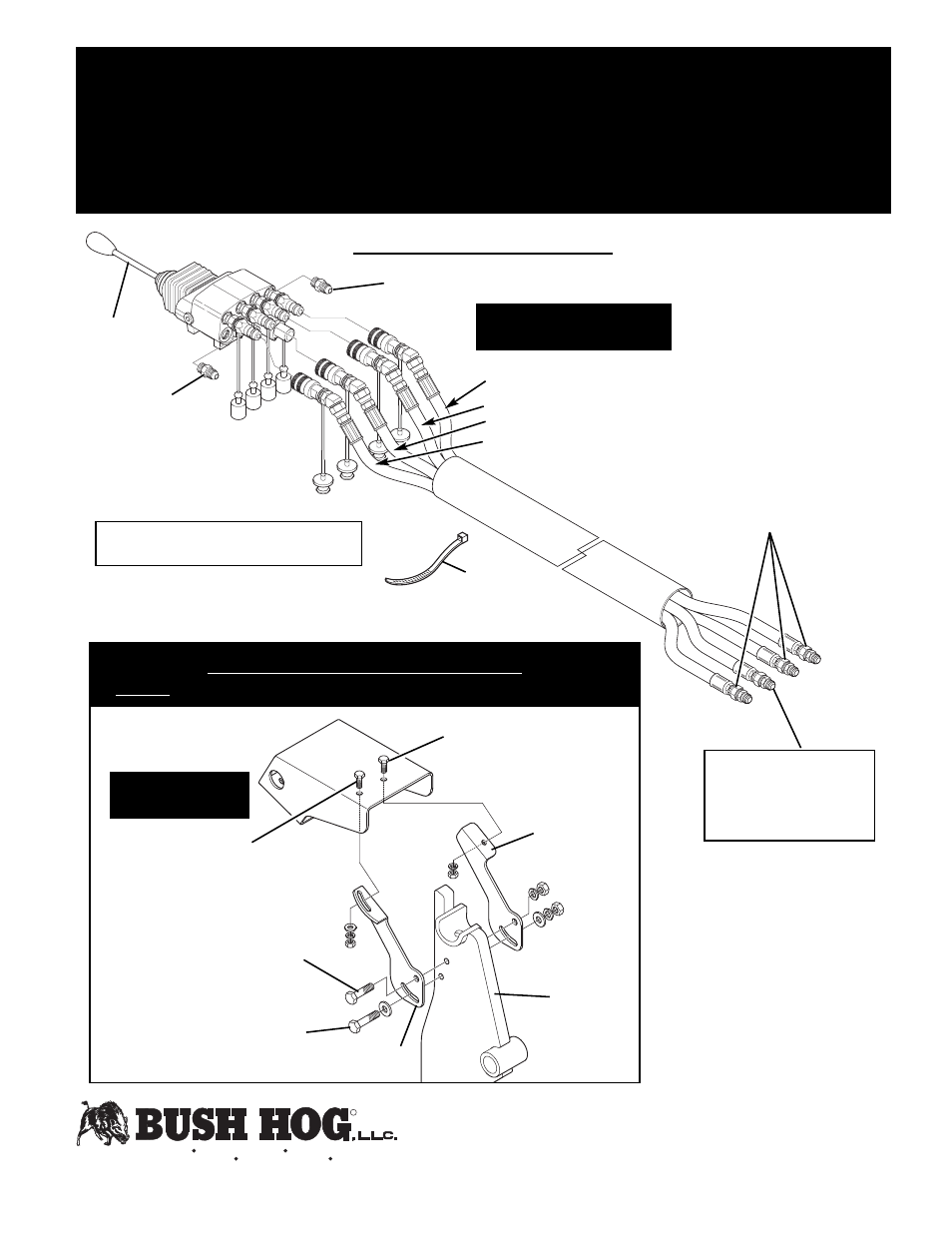
25G13603
(3) Male Unions
Connect to metal
lines on loader
Red - Rod End of Lift Cylinder
Red
Blue
Yellow
Green
Green - Base End of Bucket Cylinder
Blue- Base End of Lift Cylinder
Yellow- Rod End of Bucket Cylinder
3050137
Male Adaptor
50032239 Flow Restrictor
Install in metal line color- coded
yellow. Flow arrow on fitting
should point toward front of
loader.
Note: Install color-coded dust caps and plugs
on appropriate sides of quick couplers.
50029345
Check Valve
Mount Bracket R.H. to Loader
Bracket to Mount Bracket L.H.
(1) 1/2” x 2” Capscrew
(2) 1/2” Flatwashers
(1) 1/2” Lockwasher
(1) 1/2” Hex Nut
Mount Bracket R.H. to Loader
Bracket to Mount Bracket L.H.
(1) 1/2” x 1-3/4” Capscrew
(1) 1/2” Lockwasher
(1) 1/2” Hex Nut
Valve Mount to Mount Bracket R.H.
(1) 3/8” x 1” Capscrew
(1) 3/8” Flatwasher
(1) 3/8” Lockwasher
(1) 3/8” Hex Nut
Valve Mount to Mount Bracket L.H.
(1) 3/8” x 1” Capscrew
(1) 3/8” Lockwasher
(1) 3/8” Hex Nut
50031316
Mount Bracket R.H
.
50031317
Mount Bracket L.H.
Loader
Bracket
50041044 VALVE STAND ASSEMBLY
NOTE: Must be mounted to Loader Bracket before mounting Loader to Bracket.
Shield Not Shown for Clarity!
Valve and Hoses Not
Shown for Clarity!
25H50807
Handle Assy.
Page 1
06/14/06
ECR 08-03
Instruction Sheet No. 50032448
VALVE MOUNTING INSTRUCTIONS
FOR WALVOIL VALVE
50032443 SERIES VALVE & MOUNT KIT
HYDRAULIC ATTACHMENT
VALVE PLUMBING ASSEMBLY
52161
(5) Cable Ties
R
P.O. Box 1039 Selma, AL 36702-1039 (334) 874-2700
101 Bush Hog Boulevard Telford, TN 37690-2421 (423) 788-7100