Telescope assembly – Bushnell 78.9565 User Manual
Page 2
STANDARD EQUIPMENT
•
Refractor Telescope Assembly
•
Equatorial Mount
•
Variable Height-Aluminum Tripod
•
Exclusive Penta Mirror Assembly
•
8mm, 12.5mm, 20mm focal length - Eyepieces.
•
Red Dot Finderscope
•
Accessory Tray
•
1.5x Erecting Lens
•
3x Barlow
•
Hardware Packet—(3) Tripod Bolts with Wing Nuts, (3) Short
Accessory Tray Bolts with Wing Nuts, (3) Tripod Leg Lock
Screws
Fig. 1
T
ELESCOPE ASSEMBLY
1.
Remove all components from the carton and identify all components. It is a good idea to lay all the
parts out in front of you before assembly. READ THROUGH ASSEMBLY INSTRUCTION BEFORE YOU
ASSEMBLE YOUR TELESCOPE. The only tool required in setting up your telescope is a slotted or
Phillips blade screwdriver. Since your telescope is a precision optical system the parts require
careful handling--particularly the telescope, eyepieces, and various accessory lenses.
2.
Set-Up Tripod
•
Select one tripod leg. Loosen
Tripod Leg Lock Screw (8)
and extend the
Tripod Leg Middle Section (12).
For
a moment, do not extend the leg fully...a shorter leg is less awkward to work with during set-up. Tighten
the
Tripod Leg lock Screw
so that the
Middle Section
is securely in place. Repeat for the remaining two
legs.
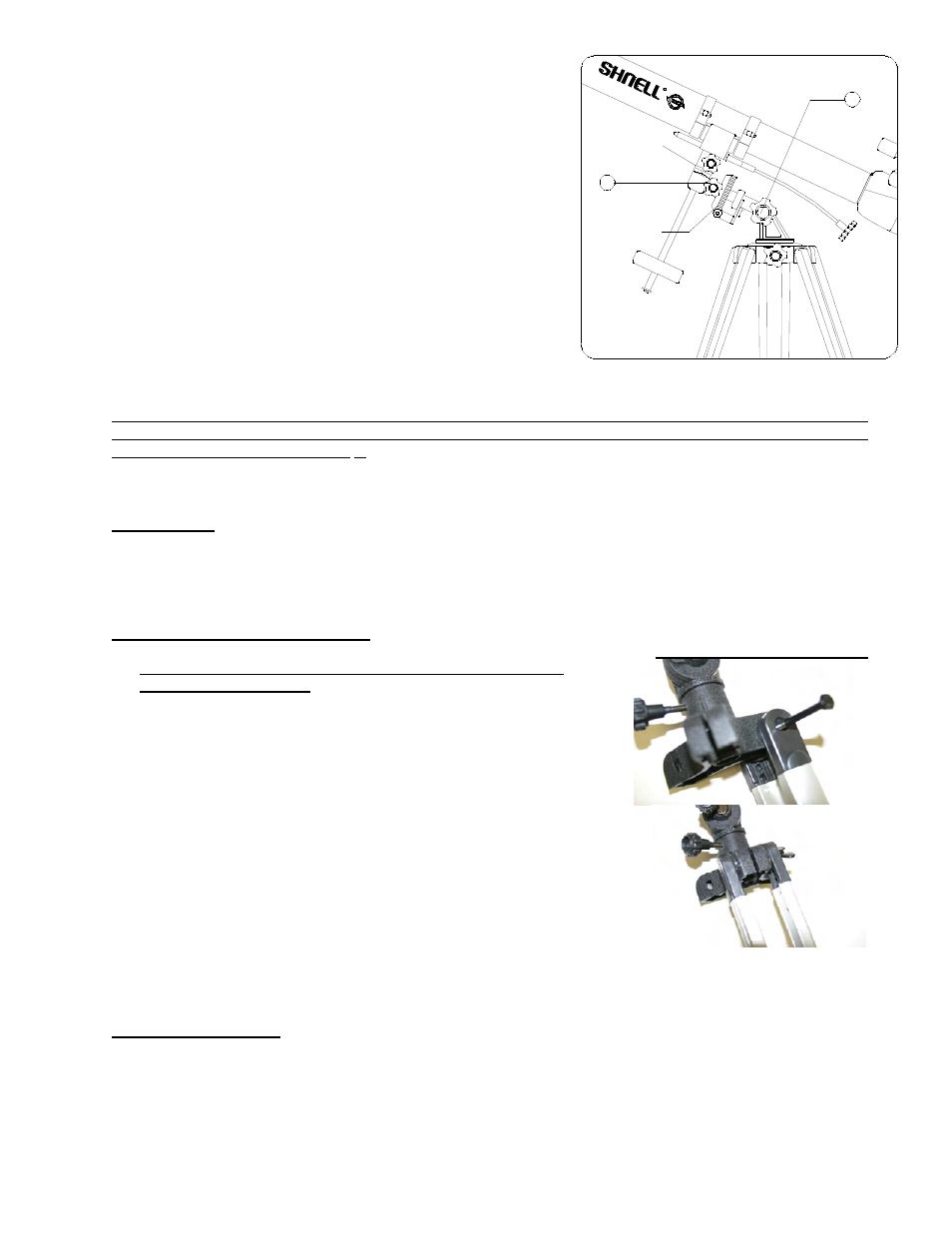
3.
Attach Telescope and Finderscope
•
Locate the pre-assembled
Telescope Main Tube (2)
and
Equatorial Mount.
Note: Before assembling tripod
legs to
Equatorial Mount, make sure the Accessory Tray
Braces (10) face inward.
Carefully remove
Telescope Main
Tube
from
Cradles.
Position the mount between
Tripod Leg
as
shown
(fig. 2).
Secure
Equatorial Mount
to
Tripod Leg using
tripod bolts
. Repeat on the remaining two
Tripod Legs
. Once
you have attached all
Tripod Legs
to the mount, securely
tighten all wing nuts and place
Telescope Main Tube
back into
Cradles
.
•
Remove plastic insert on bottom side of finderscope to allow
battery to make connection with battery contact for power.
Turn power switch on. See finderscope page.
•
Look through main telescope tube at low power and establish
a well-defined stationary target. Looking through red dot
finderscope, alternate tightening each adjustment wheel (at
rear and left side of finderscope) until the red dot of
finderscope is precisely aligned and centered on the same
object being viewed in main telescope tube. See finderscope
page.
4.
Attach Accessory Tray
Locate the
Accessory Tray (11).
Using the accessory tray bolts, wingnuts and washers connect the
Accessory
Tray to
the
Accessory Tray Braces (10)
. Start with one tripod leg and attach wingnuts. Wingnuts should be
positioned beneath the accessory tray. Do not tighten wingnuts until all
Accessory Tray Braces
are attached,
as some adjustments may be required.
Fig. 2
R
4
Declination Axis
Right Ascension
Scale
7