Px-16 – Bakers Pride P-48S Manual User Manual
Page 12
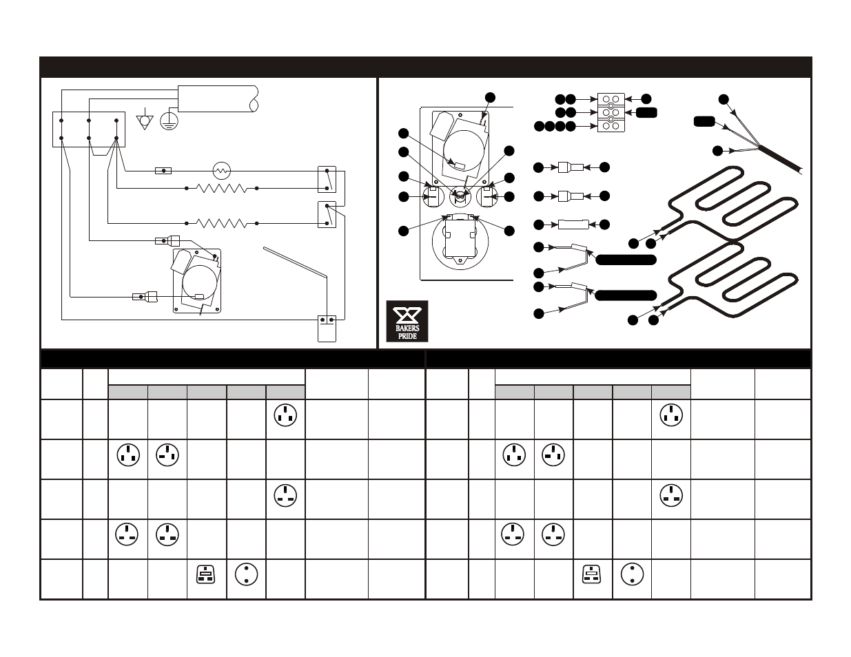
PX-16
PX-14
PX-14 & PX-16 WIRING DIAGRAM & TABLES
To Top Switch
To Bottom Switch
Line C
o dr
T p
E e
me
o
l
nt
m
Bot
to
Ele
men
t
Q1-Connector
Q2-Connector
Q3-Butt Connector
Q4-Twin Adapter Terminal
Q5-Twin Adapter Terminal
Terminal Block
z
Bu
z
er
Timer
Motor
Bottom
Switch
Top
Switch
Pilot Light
os
t
Th
er
m
at
1
1
2
2
T1 A3
A1 H4
A1 H1 H2 C1
L2 (N)
GND
L2
L1
L1
H1
S2
H2
S1
T1
C1
H4
A4
H1
H5
H3
H5
E2
E3
H1
E2
Q5
S2
H3
A4
E3
Q4
S1
A3
Brn-S1
Brn-S2
Brn
H5
Top Heating Coil
Bottom Heating Coil
Bottom
Switch
Blu-H4
Q1-P1085A
A4
uz
ze
r
B
Timer
Motor
H1
Q2-P1085A
Brn-T1
Brn
H3
Brn-A3
Thermostat 1 2
NOTE: All wires to be 14 AWG 600V 200°C.
Color as shown above.
Brn
Blu
Grn/Yel
(Blk)
(Wht)
(Grn)
or:
-Line Cord-
For NEMA plugs see tables
L1
L2 (N)
A1
Blu
Terminal
Block
Gnd
Pilot
Light
C1
P1069A E2 Gry
Top
Switch
E3 Gry
Blu Q3-Butt Connector
Blu-H1
Blu-H2
Heating Coils
Watts / Volts
Timer Motor
Volts / Hz
Volts A/C
/ Phase
Amp
USA
Canada
UK
Europe Japan
Heating Coils
Watts / Volts
Timer Motor
Volts / Hz
Volts A/C
/ Phase
Amp
USA
Canada
UK
Europe Japan
100/1
100/1
15
120/1
120/1
12.5
200/1
200/1
7.5
208-240/1
208-240/1
220-240/1
220-240/1
8.1
8.1
750/100
750/110
750/200
750/220
750/220
120/60
120/60
250/60
250/60
250/60
18
15
9
9.7
9.7
900/100
900/100
900/200
900/220
900/220
125/60
125/60
250/60
250/60
250/60
NEMA Plug Configuration & Number
NEMA Plug Configuration & Number
5-15P
5-15P
5-20P
6-15P
6-15P
6-15P
BS 1363A CEE7-VII
5-15P
5-15P
5-20P
6-15P
6-15P
6-15P
BS 1363A CEE7-VII
1
2