Pg-5000 digital pressure gauge, Option tables, Ordering information – APG PG-5000 datasheet User Manual
Page 4
4
Automation Products Group, Inc.
1025 West 1700 North
Tel. 1/888/525-7300
Logan, UT 84321 USA
Fax 1/435/753-7490
w w w . a p g s e n s o r s . c o m
s a l e s @ a p g s e n s o r s . c o m
PG-5000 Digital Pressure Gauge
APG
Automation Products Group, Inc.
®
■
Option Tables
Unit of Measure Table
There are 9 choices available:
psi
▲
kPa
inHg
bar
inH2O*
kgcm
2
mbar*
mmHg*
fsw
*Requires G2 option.
Other units of measure available.
Pressure Type Table
G
▲
Gauge
G2
High resolution gauge
CG
Compound gauge
V
Vac
A
Absolute
S
Sealed
Port Table
F0
▲
Bottom
F1
Rear
F2
Bottom with 0
2
clean
F3
Rear with 0
2
clean
F5
Remote transducer with mV sensor
F6
Rear port with panel bracket installed
F7
Bottom port with rubber boot installed
Operation Table
Operation
Electrical Connector
L0
▲
9 V battery
E0
L1
4-20 mA output
E1
L2
0-2 VDC output
E2
L3
0-5 VDC output
E1
L4
External power
E2
Option A4 is not available with option L1, L3 or L4.
Electrical Cable Length Table
Cable Length
W0
▲
0 ft.
W1
2 ft. (0.6 m)
W2
5 ft. (1.5 m)
W3
10 ft. (3 m)
W4
25 ft. (7.6 m)
W5
50 ft. (15.2 m)
Process Connection Table
P0
▲
1/4-18 NPTM
P2
1 1/2 in. sanitary
P5
1/4-18 NPTF
P7
7/16-20 SAE male
P14
1/8-27 NPTM
P16
PT 1/4 (BSPM 1/4)
P22
G3/8 (3/8 BSPP) male
Other options available.
Accessories
Please order separately, by part number. When ordering a flange or boot as an accessory, they
will not be installed on the gauge.
■
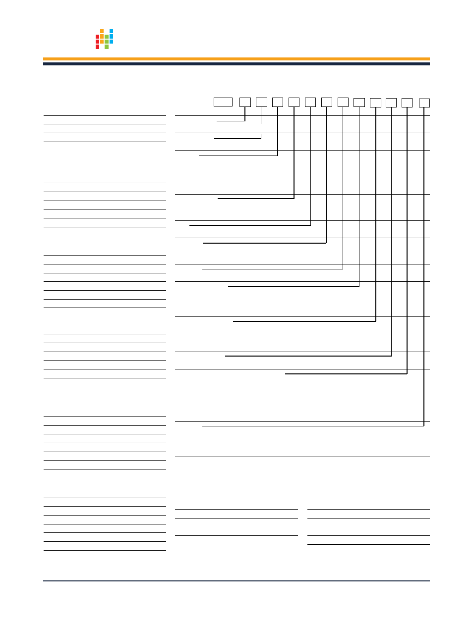
Ordering Information
PG-5000 –
Range
–
–
–
–
–
–
–
–
–
–
–
–
Unit of Measure
___
See Unit of Measure Table
Pressure Type
G-S
See Pressure Type Table
Auto Off
A0
▲
No auto off
A3
8 minute auto off
A4
16 minute auto off
A5
32 minute auto off
Zero Adjustment
Z0
▲
Cover screw
Z1
Z knob
Port
F0-F7
See Port Table
Peak Hold
H0
▲
No peak hold
H1
Peak hold
Operation
L0-L4
See Operation Table
Electrical Connection
E0
▲
No connector
E1
6 pin circular (Mating connector sold separately. See accessories.)
E2
1/8 in., 3-conductor external power and mate
Electrical Cable Length
W0
0 ft. (Use with E1, E2 (no cable) connections)
Mating connectors (E1) with cable. See accessories.
W1-W5
Use with E2 connection. See Electrical Cable Length Table
Process Connection
P0-P22
See Process Connection Table
Accuracy (see Linear Accuracy Chart for details)
N0
▲
±0.25%
N1
±0.25% with NIST certification (selected ranges)
N2
±0.1% with NIST certification (select ranges)
N3
±1% or better
N4
±1% or better with NIST certification
Materials
M0
▲
15-5 SS
M1
316L SS (under 100 psi, 316L SS/Hastelloy
®
)
Consult factory for other material options.
▲
This option is standard.
Description
Part Number
Panel mount flange (rear port only)
512598
AC to DC external power supply
(includes E2 mating connector)
511641
Rubber boot
512625
Description
Part Number
6-pin circular mating connector (E1)
509110
6-pin circular mating connector (E1)
with cable (see note below)
509110-X0XX*
*To order a 6-pin circular mating connector with cable,
you will need to specify the operation and cable length.
Specify operation: L1=1, L3=2;
Specify cable: 2, 10, 25 or 50 ft.
Example: 509110-1025 is a 4/20 mA output with 25 ft. cable