APG LF Series user manual User Manual
Page 6
Model LFP-V
Rev. A1, 4/07
6
Automation Products Group, Inc.
APG...Providing tailored solutions for measurement applications
Tel: 1/888/525-7300 • Fax: 1/435/753-7490 • www.apgsensors.com • [email protected]
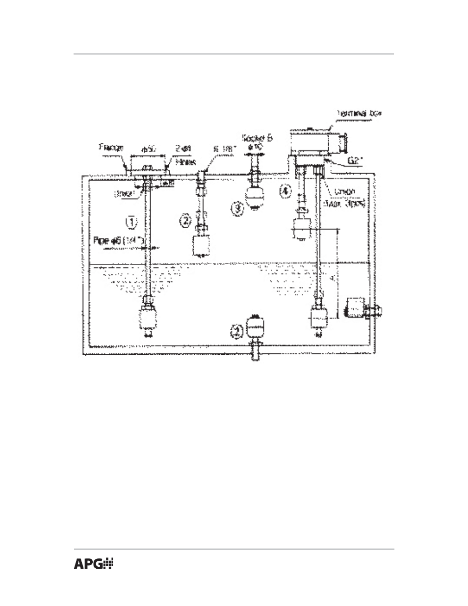
Installation
Install the LFP vertically with the lead wires up and down.
1. LFP Flange: Open holes (as specifi ed) on the tank top. Insert fl oat and
tighten the nut. Be sure to use a suitable gasket, O-ring, or thread tape.
Use a 1/4” pipe for the extension.
2. Threaded: Provide R1/8” or G1/8” female thread. Use suitable O-ring or
thread tape.
3. Bulkhead: Drill a 10 mm hole in tank top. Insert and tighten the nut. Use
a suitable O-ring or thread tape.
4. Terminal Box: Provide G2” female mounting boss. Use suitable O-ring or
thread tape. Minimum distance of operating pint (A) is 70 mm.
Note: After assembling the extension pipe, check insulation (100 MW or
more) and switch operation. Improper assembly or seal may result in damage
or injury.
- LPU-2127 user manual (27 pages)
- LPU-2428 user manual (36 pages)
- MNU Modbus Sensor user manual (40 pages)
- LOE Tank Cloud Master Sensor user manual (36 pages)
- IRU-2000 datasheet (4 pages)
- IRU-3000 datasheet (4 pages)
- IRU-2000 user manual (42 pages)
- IRU-2420 datasheet (4 pages)
- IRU-3430 datasheet (4 pages)
- IRU-5000 datasheet (4 pages)
- IRU-6429 datasheet (4 pages)
- IRU-9400 datasheet (4 pages)
- IRU-3000 user manual (28 pages)
- DST Sensors datasheet (4 pages)
- PT-L1-C datasheet (4 pages)
- PT-L1-C user manual (8 pages)
- PT-L3-C user manual (8 pages)
- PT-L10-C user manual (8 pages)
- PT-L9 datasheet (4 pages)
- PT-L9 user manual (8 pages)
- PT-400 datasheet (4 pages)
- PT-400 user manual (17 pages)
- Hammer Union Pressure Tansmitter datasheet (4 pages)
- Hammer Union Pressure Tansmitter user manual (13 pages)
- PG5 datasheet (4 pages)
- PG5 user manual (28 pages)
- PG7 datasheet (4 pages)
- PG7 user manual (31 pages)
- PG10 datasheet (4 pages)
- PG10 user manual (42 pages)
- PT-500 datasheet (4 pages)
- PT-500 user manual (16 pages)
- PT-500 Modbus user manual (32 pages)
- PT-503 datasheet (3 pages)
- KA Cable Suspended datasheet (6 pages)
- KA Cable Suspended user manual (18 pages)
- FT-100 Cable Suspended datasheet (4 pages)
- FT-100 Cable Suspended user manual (8 pages)
- FL Series datasheet (4 pages)
- FLE Series user manual (12 pages)
- FLR Series user manual (28 pages)
- FLX datasheet (4 pages)
- FLX user manual (16 pages)
- LF Series datasheet (10 pages)
- LFE Series user manual (8 pages)