APG LF Series user manual User Manual
Page 5
Rev. A1, 4/07
Model LFP-V
5
Automation Products Group, Inc.
APG...Providing tailored solutions for measurement applications
Tel: 1/888/525-7300 • Fax: 1/435/753-7490 • www.apgsensors.com • [email protected]
• Installation
Environment
The LFP should be installed in an area that meets the following conditions:
• Within the specifi ed temperature range.
• Located away from any strong magnetic fi eld.
• Located away from drop, splash or vapor around the lead wire egress.
Note: Apply the proper sealing compound over the lead wire egress if
necessary. Liquid penetration may ruin insulation.
• Clean liquid, free from any foreign matter.
• Ample space for maintenance/inspection.
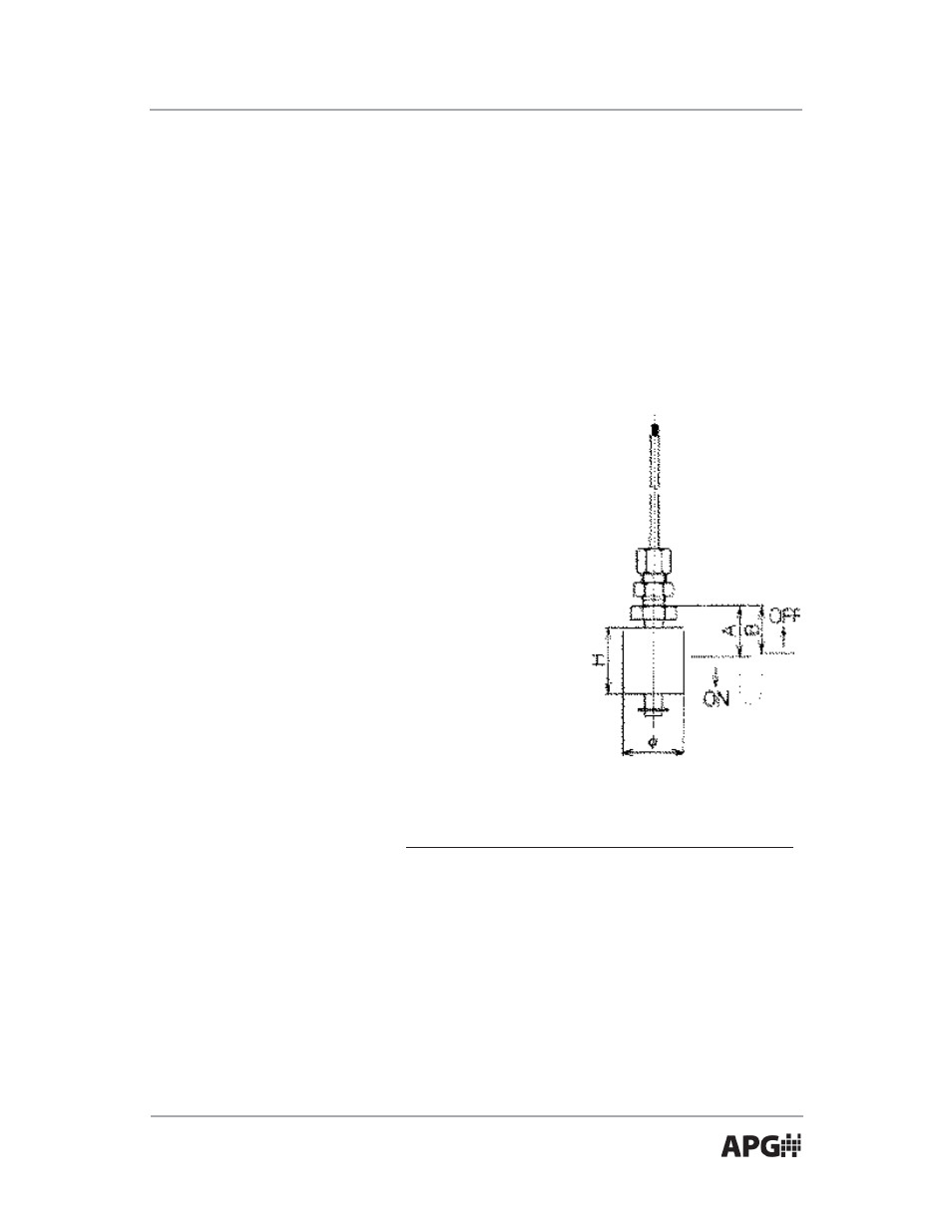
Location
Point of operation in SG = 1.0 (water)
LFP-V-2A
LFP-V-2B
LFP-V-2P
LFP-V-2F
A: Switch closes at level falls
24.5
21.5
20.0
19.0
B: Switch opens as level rises
23.0
20.0
18.5
17.5
Size of fl oat
ø25 x H25 ø25 x H25 ø25 x H25 ø25 x H25
Note: Standard switch operation is NC (switch closes as the level falls).
Switch action can be reversed by inverting the fl oat. The direction of close is
marked on the fl oat.
DO NOT locate near liquid inlets/outlets.
If there is surface wave motion, use a time delay
relay to dampen the switch action.