Installation – APG FLE Series user manual User Manual
Page 6
FLE Series
Rev. A3, 10/08
6
Automation Products Group, Inc.
APG...Providing tailored solutions for measurement applications
Tel: 1/888/525-7300 • Fax: 1/435/753-7490 • www.apgsensors.com • [email protected]
• Installation
- Location -
Do not locate the FLE series sensor near inlets/outlets.
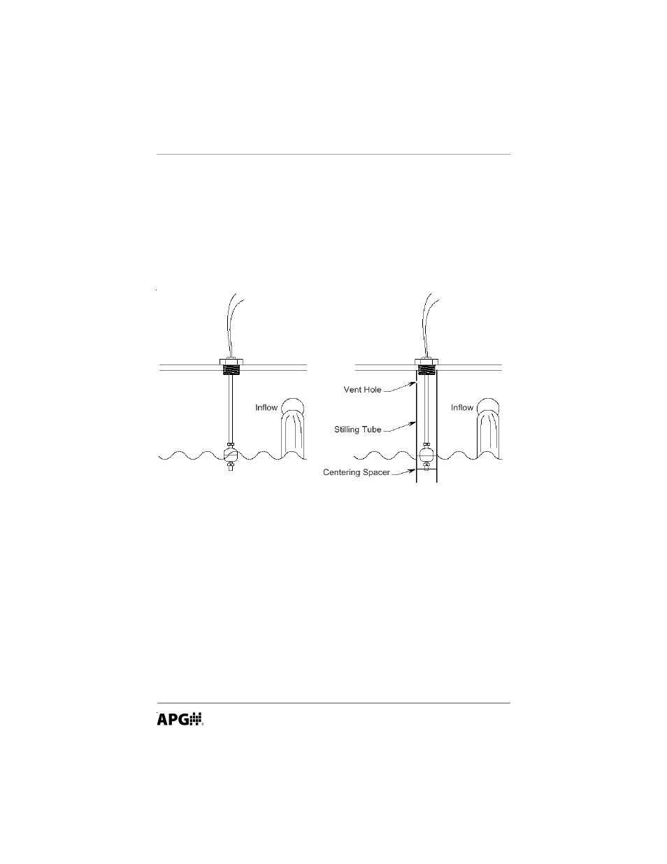
If there is surface wave action, then use a time-delay relay or stilling tube. If a
stilling tube is used, drill vent holes in the tube and use a centering spacer on
the bottom of the stem to assure the float has free travel inside the tube.
Wave action may cause switch to chatter.
Use a stilling tube or time-delay
relay to prevent switch chatter.
- Mounting -
The FLE can be mounted up to 30
0
from vertical.
1. Flange Mounting
Provide the compatible mating flange on the tank and install using a suitable
gasket.
2. Plug Mounting
Provide the compatible female boss on the tank and install the FLE with a
suitable gasket, O-ring, or thread tape.
- LPU-2127 user manual (27 pages)
- LPU-2428 user manual (36 pages)
- MNU Modbus Sensor user manual (40 pages)
- LOE Tank Cloud Master Sensor user manual (36 pages)
- IRU-2000 datasheet (4 pages)
- IRU-3000 datasheet (4 pages)
- IRU-2000 user manual (42 pages)
- IRU-2420 datasheet (4 pages)
- IRU-3430 datasheet (4 pages)
- IRU-5000 datasheet (4 pages)
- IRU-6429 datasheet (4 pages)
- IRU-9400 datasheet (4 pages)
- IRU-3000 user manual (28 pages)
- DST Sensors datasheet (4 pages)
- PT-L1-C datasheet (4 pages)
- PT-L1-C user manual (8 pages)
- PT-L3-C user manual (8 pages)
- PT-L10-C user manual (8 pages)
- PT-L9 datasheet (4 pages)
- PT-L9 user manual (8 pages)
- PT-400 datasheet (4 pages)
- PT-400 user manual (17 pages)
- Hammer Union Pressure Tansmitter datasheet (4 pages)
- Hammer Union Pressure Tansmitter user manual (13 pages)
- PG5 datasheet (4 pages)
- PG5 user manual (28 pages)
- PG7 datasheet (4 pages)
- PG7 user manual (31 pages)
- PG10 datasheet (4 pages)
- PG10 user manual (42 pages)
- PT-500 datasheet (4 pages)
- PT-500 user manual (16 pages)
- PT-500 Modbus user manual (32 pages)
- PT-503 datasheet (3 pages)
- KA Cable Suspended datasheet (6 pages)
- KA Cable Suspended user manual (18 pages)
- FT-100 Cable Suspended datasheet (4 pages)
- FT-100 Cable Suspended user manual (8 pages)
- FL Series datasheet (4 pages)
- FLR Series user manual (28 pages)
- FLX datasheet (4 pages)
- FLX user manual (16 pages)
- LF Series datasheet (10 pages)
- LFE Series user manual (8 pages)