APG PT-L10-C user manual User Manual
Page 4
PT-L10-C
Rev. A3, 10/08
4
Automation Products Group, Inc.
APG...Providing tailored solutions for measurement applications
Tel: 1/888/525-7300 • Fax: 1/435/753-7490 • www.apgsensors.com • [email protected]
•
Instructions
All units are factory calibrated prior to shipment.
1. Zero Trimming
If it becomes necessary to re-adjust “zero”, this can be accomplished by
adjusting the trimpot marked “Z”. An ideal zero is indicated by an output of
0 VDC.
A. Remove the knurled nut. If your transducer does not have a knurled nut,
your transducer can not be field adjusted. You can return the transducer
to the factory for repair and/or adjustment.
B. Carefully remove the connector or pigtail from the body of the transducer
and pull it all the way out so that the amplifier board is exposed. Do not
over extend the ribbon cable that attaches the amplifier board to the
sensor.
C. Reconnect the device and have access to a method of monitoring the
output of the transducer.
D. Ensure that the transducer is at 0 psig or 0 psia (vacuum if absolute)
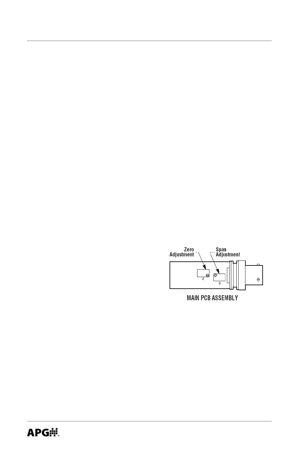
E. Using a jewelers screwdriver or a suitable instrument, adjust the “Z” pot
until you have 0 VDC output. Do not
make changes to the Span
adjustment (the “S” pot to the right
of the push button) as part of the zero
trimming. The Span should only be
changed as part of the re-calibration
of a transducer with a known pressure
source.
2. Re-calibration
This procedure requires a known pressure source of at least ±0.1% accuracy
in order to fully utilize the accuracy potential of the transducer. (If not available,
you can return it to the factory for re-calibration.)
Procedure:
A. Ensure that the transducer is at 0 psig or 0 psia (vacuum if absolute), and
adjust zero as per instructions in #1.
B. Apply full scale pressure to the pressure port and adjust the span (“S”)
pot until full scale signal of 10 VDC is reached.