Caution, Ventilation evaluation, Control board operation – Bryant Energy/Heat Recovery Ventilator ERVBBSVA1100 User Manual
Page 8: Care and maintenance, Ventilator sizing, Defrost, Off and intermittent/off mode, High--speed air exchange, Low--speed air exchange, Door
8
VENTILATION EVALUATION
UNIT DAMAGE HAZARD
Failure to follow this caution may result in reduced unit
efficiency, capacity or unit life.
DO NOT use HRV during construction of a house or when
sanding drywall. This type of dust may damage system.
CAUTION
!
Ventilator Sizing
Tables 3 and 4 should be used to determine the required airflow for
a home. These guidelines are taken from ASHRAE 62.2--2004.
Table 3 – Ventilation Air Requirements, cfm
FLOOR
AREA (ft
2
)
BEDROOMS
0---1
2---3
4---5
6---7
>7
<1500
30
45
60
75
90
1501---3000
45
60
75
90
105
3001---4500
60
75
90
105
120
4501---6000
75
90
105
120
135
6001---7500
90
105
120
135
150
>7500
105
120
135
150
165
Table 4 – Ventilation Air Requirements, L/s
FLOOR
AREA (m
2
)
BEDROOMS
0---1
2---3
4---5
6---7
>7
<139
14
21
28
35
42
139.1---279
21
28
35
42
50
279.1---418
28
35
42
50
57
418.1---557
35
42
50
57
64
557.1---697
42
50
57
64
71
>697
50
57
64
71
78
CONTROL BOARD OPERATION
Defrost
The ERV/HRV continually monitors the outside air temperature. If
the outside air is at or below 23°F (--5°C), the ERV/HRV will
initiate a defrost cycle by closing the outside air damper and
recirculating warm indoor air through the heat recovery core. This
happens every 32 minutes with a 6 minute defrost cycle. During
this process, core is defrosted without the use of electric strip heat.
At 5°F (--15°C), unit will defrost for 6 minutes every 32 minutes.
At --17°F (--27°C), the unit will sense a need to defrost every 20
minutes with a 6 minute cycle. See the Troubleshooting section for
a control logic explanation.
Off and Intermittent/Off Mode
When ERV/HRV is Off, K1 relay is open, and K5 relay is
energized which closes outside air damper.
High--Speed Air Exchange
When high--speed air exchange occurs, K1 and K2 relays are
energized and K5 relay is de--energized. This opens low--speed
contacts, and closes high--speed contact on K2 relay. This also
opens contact on K5 relay which opens outside air damper. Then,
115VAC is applied between orange and gray wires on Molex plug
(pins 1 and 6) and blower motor runs in high--speed operation.
Low--Speed Air Exchange
When low--speed air exchange occurs, K1 Relay is energized
which closes the contacts. K2 and K5 relays are de--energized. This
keeps low--speed contacts closed and high--speed contacts open on
K2 relay, and opens outdoor air damper. 120VAC is applied
between Red and Gray wires on Molex plug (pins 1 and 4) and
blower motor runs in low--speed operation.
CARE AND MAINTENANCE
Door
ERV/HRV door can be removed by unlatching brief case style
latches, then slide door to the right and remove it from hinges.
Door must be in place and secured shut for proper operation.
Filter
Filters in ERV/HRV are washable and should be cleaned every 3
months. Use a vacuum cleaner to remove heaviest portion of
accumulated dust, then wash in lukewarm water. Allow filter to
completely dry before reinstalling. A dirty air filter will cause
excessive strain on blower motor. Never operate unit without a
filter. Vacuum out debris.
In addition, regularly check and clean screens on exterior intake
and exhaust hoods when necessary.
UNIT COMPONENT DAMAGE HAZARD
Failure to follow this caution may result in unit component
damage.
DO NOT clean filters in a dishwasher and DO NOT dry
them with a heating appliance or permanent damage will
result.
CAUTION
!
Blower Motor and Wheel
ERV/HRV blower motors are factory lubricated for life.
Lubricating bearings is not recommended. However, inspect and
clean any accumulated dirt and grease from blower motor and
wheel annually.
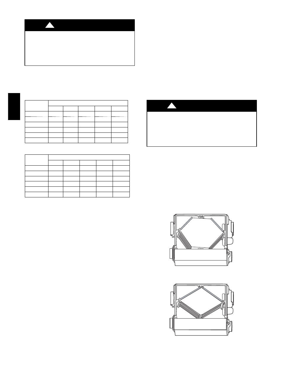
Cleaning the Core
ERV is equipped with a special energy recovery core which utilizes
a special membrane and allows transfer of sensible and latent
energy. The core should always be vacuumed only every 3 months
to remove dust and dirt that could prevent transfer of energy. (See
Fig. 15 and 16.)
A05347
Fig. 15 -- ERV Ports on Side (Bottom View)
A05348
Fig. 16 -- HRV Ports on Side (Bottom View)
ER
V
/HR
V