Allen h eath, Aux output jack sockets, Mix l r insert jack sockets – Allen&Heath ZED-16FX User Manual
Page 23: Main l r output xlr sockets, Mono output jack socket, Headphones jack sockets, 48v phantom power switch, Left right meters, Footswitch connection
Allen & Heath 23 ZED-12FX, 16FX & 22FX User Guide
MASTER SECTION
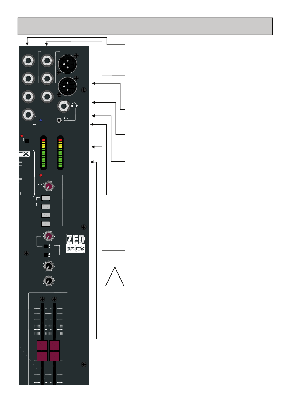
Aux output jack sockets
Standard 1/4” jack sockets for Aux 1 to 3 outputs (FX or Aux 4 is
the internal Effects bus and does not have an output socket. Imped-
ance balanced, nominal level = 0dBu.
Mix L R Insert jack sockets
Standard 1/4” (6.25mm) Jack sockets for unbalanced insert send and
return signals. Wired Tip = send, Ring = return, Sleeve = Chassis.
Nominal level is 0dBu.
Main L R output xlr sockets
Main left & right outputs. Impedance balanced signals, pin1 = chassis,
pin2 = hot (+), pin3 = cold (-). Nominal level = 0dBu.
Mono output jack socket
A mono sum of the main left & right post-fade signals.
Headphones jack sockets
One 1/4” and one 3.5mm jack socket for stereo headphones. Wired
Tip = left, Ring = right, Sleeve = Chassis.
It is recommended that headphones with an impedance higher than
30ohms are used.
48v Phantom Power switch
Press this in to switch 48v Phantom Power to all the Mic input xlr
connectors, if any of the microphones attached require power. Dy-
namic microphones won’t mind being connected to a phantom
powered input, but care is needed to ensure that 48v is not
switched on if an xlr is used to input a signal from an electronic
circuit (ie. Another mixer or keyboard).
When switching 48v on or off, or plugging in connectors to
channels with 48v present, it is important (and normal
practise) to mute the channels. This will avoid loud clicks
and bangs potentially getting through to the amps & speak-
ers with the possible effect of damaging the speakers, or
the audience’s hearing!
Left Right meters
12 segment LED meters, peak type response, the “0” position re-
flects 0dBu at the outputs. These display the signals from the moni-
tor selector switches below, or the PFL (pre-fade listen) signals
from any selected channels, which overrides.
!
Footswitch connection
Standard 1/4” (6.25mm) Jack socket for use with a footswitch.
Wired so that a switch closure between Tip and Sleeve will activate
the effects mute circuitry to cut the effects return (and ST4) from
the main LR mix and the Aux 1 & 2 sends.
30
L
+16
-6
-9
-20
-30
-16
-12
-3
0
+3
+6
+9
R
PFL ACTIVE
MIN
MAX
PHONES
AUX1
AUX2
2TRK RTN
USB RTN
STEREO
O
O
+6
ALT
OUT
MONITOR
LR
O
O
+6
AUX1
MASTER
O
O
+6
AUX2
MASTER
5
20
10
5
0
10
POST
PRE
LR
L
R
POWER
48V
INSERT R
AUX1 OUT
PHONES
MAIN OUT
0
0
0
PHANTOM POWER
ALLEN
H
EATH
AUX2 OUT
AUX3 OUT
INSERT L
MONO OUT
+16
-6
-9
-20
-30
-16
-12
-3
0
+3
+6
+9
16
15
14
13
12
11
10
9 Plate (decay)
Plate (predly)
Plate (colour)
Hall1 (size)
Hall2 (size)
Arena (size)
Flanger (dpth)
Chorus (dpth)
F/SWITCH
FX MUTE
&