Servicing – Allen&Heath Xone 23C User Manual
Page 18
18
SERVICING
How to replace the crossfader
If the crossfader is subject to a lot of use it will, in time wear out and need replacing. Intermittent or noisy operation is
an indication that it is becoming worn. Using a propriety fader cleaner such as CaigLube might temporarily restore use,
but DO NOT use on a new fader as it will wash away the factory applied grease.
Warning! Dismantling your mixer could invalidate the warranty; if you are unsure of your ability to safely carry out this
work then it is advised that you leave it to a qualified service technician.
Tools you will need are T10, and T8 Torx screwdrivers. Ensure that the power supply has been turned off and discon-
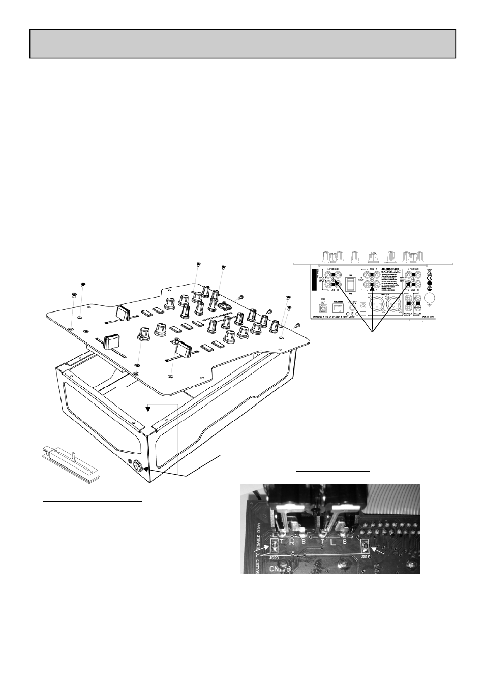
nected from the unit. Using the T10 torxdriver remove the three screws located in the centre of the channel input and
FX loop connectors (see illustration), then using the T8 torxdriver remove the 8 screws that hold the front panel to the
chassis. Now carefully lift the front edge of the panel up until the PCBs clear the chassis and pull the whole assembly
forward slightly until the connectors at the rear are free from the chassis. You can now lift the front panel up to gain
sufficient access to replace the crossfader.
If you wish to completely remove the front panel assembly you will need to unscrew the 1/4” headphone bezel using an
11mm or 7/16 AF socket, and remove the T10 screw that secures the headphone PCB to the chassis. Carefully unplug
the multi-way harness from the connector PCB and lift the front panel away from the chassis.
Reassembly is a reverse of this procedure. Take great care to ensure that no harnesses become trapped and that all
connectors are fully pushed home. Replace the screws and test the mixer for correct operation.
REMOVE THE T10 SCREWS ARROWED
Unscrew headphone bezel, and
remove T10 screw that secures
the headphone PCB to the
chassis.
To Replace the crossfader
Using the T8 driver, remove the 2 screws either
side of the crossfader and lower the crossfader
mounting plate - unplug the 4way harness from
the crossfader PCB, and unscrew the fader from
the mounting plate
The mounting plate is designed to allow for fit-
ment of the contactless Innofader and can be
fitted in two different positions depending which
fader is being fitted.
The standard fader can be ordered under A&H
part number 004-503JIT
The Innofader can be ordered under part num-
ber 004-504JIT
If the RIAA input level is too low, or you wish to convert them to Line level.
To increase the gain by 6dB, remove the resistors arrowed and link the Pads
with solder. These resistors are located on the underside of the front panel
PCB, directly behind the Input RCA connectors
To convert to Line level, remove the resistors and leave the Pads unsoldered.
RIAA input options