Installing the pl-8, Grounding metal plates, Pl-anet wiring – Allen&Heath PL-8 User Manual
Page 3: Connecting to an idr unit, End of chain termination, Programming the controls, Diagnostics, Wiring terminals, Wiring the switch closure inputs
PL-8 User Guide AP5270 issue 3
3
Installing the PL-8
Mount the assembly into a single gang backing
box located in a wall or suitable furniture. If necessary, it may be installed in a
hidden location such as a ceiling void or cupboard as it is not necessary for the
operator to have access to the module. Minimum recommended internal box
depth is 32mm. We recommend that you provide enough space in the cavity
behind the box to allow a service loop for the wiring to the module.
Grounding metal plates
Ensure that the metal face plate
is correctly grounded to ensure safety. The plate should be connected to a
local safety ground. Use a ground wire or physical contact with a grounded
back box. The same applies to any exposed metal surfaces used within the
system.
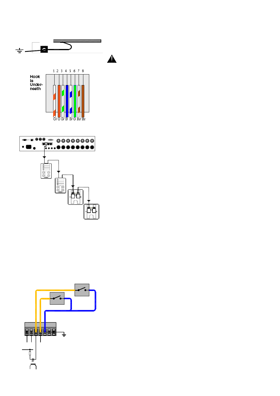
PL-Anet wiring
Use flame retardent CAT5 STP (shielded twisted pair)
cable terminated with RJ45 connectors. Do not use UTP cable. We
recommend the multi-stranded rather than solid conductor type. The
connection follows the EIA/TIA 568B wiring colour scheme. Ensure all ports
and cables in the system are wired to this scheme.
Connecting to an iDR unit
The iDR unit communicates with
the PL-8 using the PL-Anet port. This serial connection can be daisy chained
through several PL wallplates as shown. Make sure you plug the PL-Anet IN
and OUT sockets correctly.
End of chain termination
As with any RS485 system, the last PL
device needs to have a terminating resistor fitted to its output port. Each PL-8
is shipped with a terminator plug already fitted in its PL-Anet output socket.
Leave this fitted only if the unit is the last in the chain.
Programming the controls
iDR System Manager software
version V3.1 or later is required. Check the Allen & Heath web site for the latest
software. Ensure that the iDR PL-Anet port is active. Its green ‘active’ LED
should be lit. If not, use the iDR System Manager software Communications
Option menu to activate the port. Plug in the PL-Anet cable. The iDR System
Manager screen should display icons for each PL device it recognises. If you
do not have the iDR available you can configure the software off line. Refer to
the Help file for details on programming the PL functions.
Diagnostics
If a fault is suspected check the two diagnostics LEDs on
the underside of the PL-8 connector PCB. Both the red and green LEDs
should be lit once communication with the iDR is established. If a fault is
found, first check for correct wiring. If further assistance is required contact
Allen & Heath technical support.
Wiring terminals
Phoenix type screw terminal connectors are used
for connecting the external switches and logic to the PL-8. Make sure the wire
ends are carefully stripped and inserted into the terminals. Tighten the screws
using a small slotted screwdriver. To ensure interference-free operation we
recommend you use shielded cable.
Wiring the switch closure inputs
The 7way input terminal
block provides 4 switch input connections. Pins 5 to 7 ‘G’ are used as the
common switch ground. One wire can feed this ground to a bank of switches.
Two switches are shown wired in the diagram here.
The switch works by linking its connector pin to any ground (‘G’) pin. Use a
contact closure such as a momentary press switch, microswitch or relay to do
this. Low current switches may be used. We recommend good quality sealed
components for reliable operation.
The input pin is fed from the internal +5V reference supply through a 1k5 ohm
resistor. It uses an opto-coupler to isolate the PL-8 from the connected
equipment. Approximately 1.2mA minimum current flows when connected to
ground. Combined switch and cable resistance should not exceed 1k ohm for
the switch to activate.
INTERNAL PL-8 CIRCUIT
(1 OF 4 SHOWN)
2 3 4
G
1
G G
INPUTS
SWITCH
SWITCH
+5V
1K5
OPTO
OUT
IN
OUT
IN
PL-Anet
TE
RM
IN
AT
OR
PL
UG