Connecting to the idr-4(8), Fully expanded idr-4(8), Idr-in idr-out idr-8 – Allen&Heath iDR-In User Manual
Page 3: Audio out, Out dr-link
iDR-in/out User Guide AP4774
3
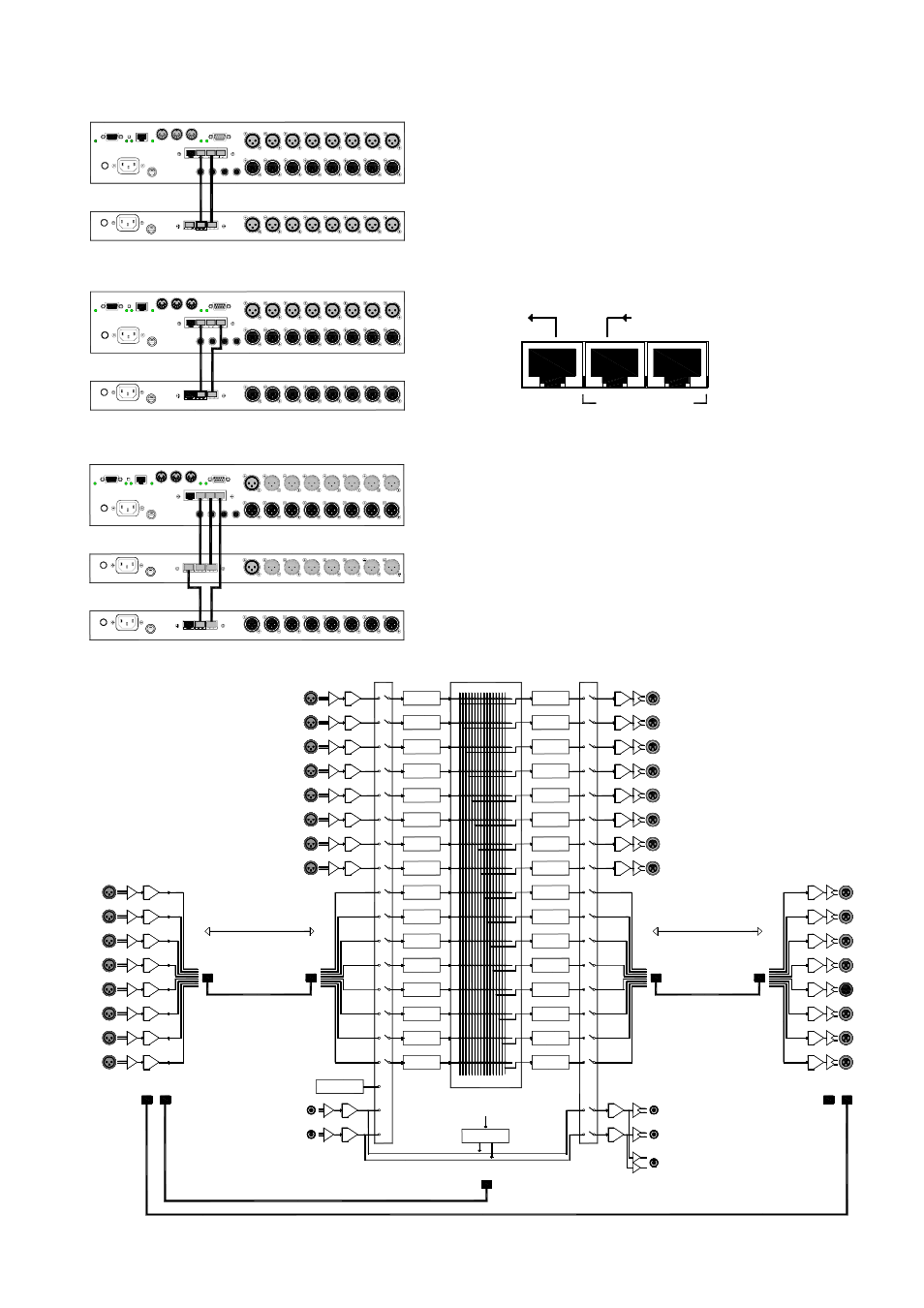
Connecting to the iDR-4(8)
You can connect
either or both expanders according to the requirements of your
application. The iDR-in AUDIO OUT connects to the iDR-4(8)
AUDIO IN. The iDR-out AUDIO IN connects to the iDR-4(8)
AUDIO OUT. Ensure that the expander DR-Link IN connects to
DR-Link on the iDR-4(8) it is associated with. If both
expanders are used with the same iDR-4(8) then daisy chain
from DR-Link OUT on one to DR-Link IN on the other. DR-Link
can also be daisy chained from or to iDR-switch units if you
are using them as well.
Fully expanded iDR-4(8)
The diagram below shows
the iDR-8 with both the input and output expanders fitted.
Note the connection of DR-Link which is daisy chained from
one unit to the next. If an iDR-switch unit is also fitted then
daisy chain DR-Link from the last expander to the switch box.
Make sure you plug into the correct DR-Link socket.
Use CAT5 STP cable. A pair of standard 2 metre cables is
provided with each expander. Maximum cable length is 250
metres. This means that the expander units can be used for
remote audio over CAT5 cable.
AUDIO OUT
next
OUT DR-LINK
previous
IN
DIGITAL EXPANDER
IN OUT
DR-
LIN
K
AUDIO
OUT
DR-
LINK
AU
DI
O
IN
iDR-in
iDR-out
iDR
8
7
6
5
4
3
2
1
8
7
6
5
4
3
2
1
IN
OUT
16
15
14
13
12
11
10
9
IN
16
15
14
13
12
11
10
9
OUT
CONNECTING BOTH EXPANDERS
IN OUT
DR-L
IN
K
AU
DI
O
OUT
iDR-in
iDR
8
7
6
5
4
3
2
1
8
7
6
5
4
3
2
1
IN
OUT
16
15
14
13
12
11
10
9
IN
CONNECTING THE INPUT EXPANDER
IN OUT
DR-
LINK
AU
DI
O
IN
iDR-out
iDR
8
7
6
5
4
3
2
1
8
7
6
5
4
3
2
1
IN
OUT
16
15
14
13
12
11
10
9
OUT
CONNECTING THE OUTPUT EXPANDER
IN
DR-Link
AUDIO OUT
AUDIO IN
CAT5
CAT5
CAT5
CAT5
250 metre max
250 metre max
INPUT
OUTPUT
AUDIO OUT
1
2
3
4
5
6
7
8
9
10
11
12
13
14
15
16
1
2
3
4
5
6
7
8
9
10
11
12
13
14
15
16
SIG GEN
ACTIVE MONITOR
iDR-in
iDR-out
iDR-8
DR-Link
AUDIO IN
OUT IN
DR-Link
OUT