8 diagnostics audio exp:in/out, Turning the expander on or off, Checking for expanders – Allen&Heath iDR D-In User Manual
Page 2: Idr-in and idr-out expanders, Power lock link
2
IDR D-in/out User Guide AP6636
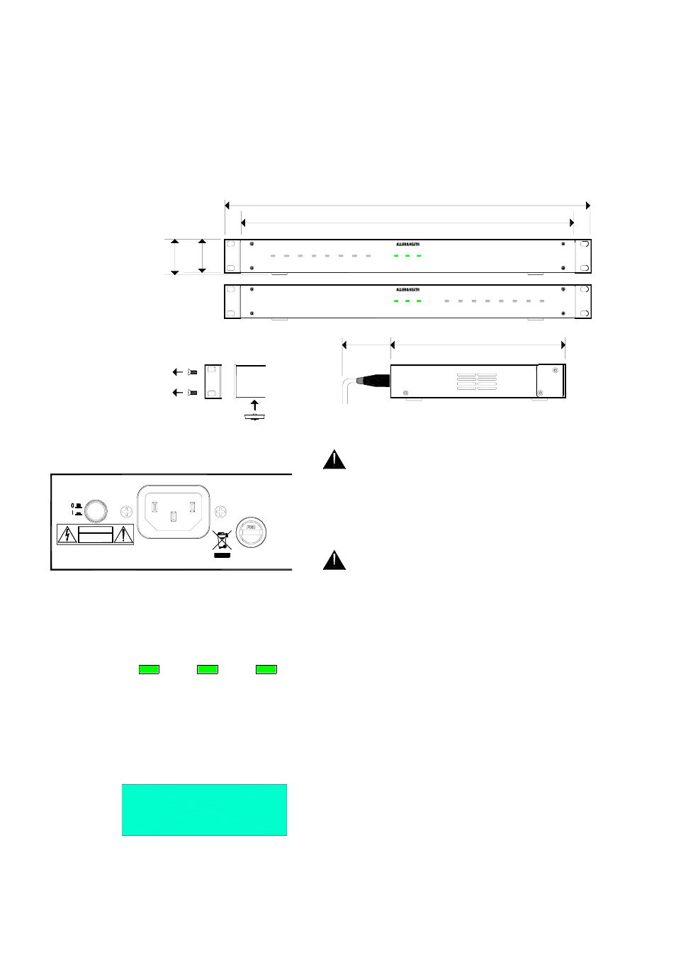
The iDR D-in and iDR D-out expanders can be rack mounted or free standing. There are
no user controls on the front panel, only the status and assignable LEDs. Allow a minimum
of 75mm clearance behind the unit for the connectors and cables. Ensure adequate
ventilation to the side of and behind the unit.
The units are shipped with their rack ears fitted and feet removed ready to be mounted in a
standard 19” equipment rack. 1U rack space is required. For desk mount operation
remove the two rack ears using a Torx (star head) T10 screwdriver. Fit the four plastic feet
provided by pressing them into the underside.
Make sure you have read the Important Safety
Instructions provided. Also check that your local mains
supply is compatible with that printed on the rear panel of
the unit. Ensure that the correct mains lead with moulded
plug and IEC connector has been supplied. For your own
safety and optimum performance make sure the system is
correctly grounded.
To avoid any unexpected audible clicks or thumps
always turn connected power amplifiers down or off before
switching the iDR or any other signal equipment on or off.
Turning the expander on or off
First make sure
the unit is correctly plugged up and connected to the iDR-4(8).
This is described below. Turn the unit on by pressing the rear
panel power ON/OFF switch. The power LED lights up. The
link LED lights if the DR-Link connection is established with the
iDR-4(8). The lock LED lights once the link is established and
audio is correctly communicated with the iDR-4(8). The iDR
System Manager detects the presence of the expander.
If one or more of the LEDs do not light then check that the
cables are correctly fitted and the iDR-4(8) is functioning
normally.
Checking for expanders
You can use the front
panel iDR-4(8) Setup menus to check if any expanders are
connected and recognised. This is useful when the expanders
are located far away from the main unit. With the face plate
removed access menu *8 Diagnostics and scroll to Audio Exp.
Refer to the iDR-4 user guide AP5230 or iDR-8 user guide
AP4530 for further details.
power
lock
link
AUDIO INPUT EXPANDER
power
lock
link
iDR-in
lock
link
power
AUDIO OUTPUT EXPANDER
iDR-out
48mm
1.9"
44mm
1.7"
1U
232mm
9.1"
307mm
12"
75mm
3"
iDR-in and iDR-out EXPANDERS
Remove 2x rack ears
Fit 4x feet
M3 Torx T10
483mm
19"
443mm
17.4"
*8 Diagnostics
Audio Exp:In/Out
FUSE: T500mA L
250V 20mm
100 - 240V~
47-63Hz ~ 25W MAX
THIS APPARATUS MUST BE EARTHED.
CET APPAREIL DOIT ETRE MIS A LA TERRE
DO NOT OPEN
CAUTION
RISK OF ELECTRIC SHOCK
AVIS: RISQUE DE CHOC ELECTRIQUE - NE PAS OUVRIR.
Laite on liitettävä suojamaadoituskoskettimilla varustettuun pistorasiaan
Apparatet må tilkoples jordet stikkontakt
Apparaten skall anslutas till jordat uttag
REPLACE FUSE WITH SAME TYPE AN
FOR CONTINUED PROTECTION AGAIN
ATTENTION: REMPLACER PAR UN FU