Allen&Heath WZ20 8 2 SERVICE MANUAL User Manual
Page 10
ALLEN & HEATH
2E-8SM
9
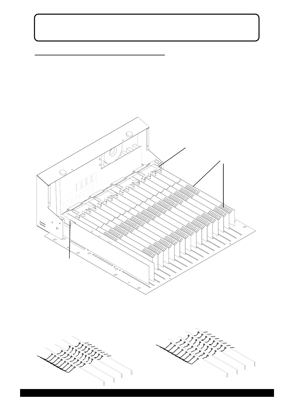
Access to the input channel circuit board options can be achieved at this stage by carefully cutting
and resoldering the link options as necessary. It is not necessary to completely remove the circuit
board assembly to change the options.
Refer to the section INTERNAL LINK OPTIONS for more details.
Unit inverted with the base and connector cover removed.
BUSS WIRES
C
To completely remove a circuit board assembly
4.) Identify the circuit board assembly to be removed and then cut the buss wires half way between each circuit
board. Disconnect the flexible flat cable (C) plugged into the connectors mounted along the edge of the circuit
board. If removing the LEFT or RIGHT circuit board assembly, the ribbon cable (D) and flexible flat cable
(E) will have to be carefully unplugged as well.
5.) The circuit board can now be removed.
When all service work is complete, remove all debris such as solder, component legs and wire clippings from inside the
console and check your work carefully before reassembly. To refit the circuit assembly follow the above procedure in
reverse order. Make sure all harnesses are correctly aligned and plugged on. Test for correct operation.
Cut each wire
in the centre
Overlap
and
solder
Buss wires
D
LEFT
RIGHT
MONO
STEREO