Appendix b: alarm i/o connector – AirLive FE-200DM User Manual
Page 49
5. Appendix
AirLive FE-200DM Manual
43
Appendix B: Alarm I/O Connector
This Network Camera provides a general I/O terminal block as below:
Pin Function
Description
1 GND
2 Digital input 4
3 Digital input 3
4 Digital input 2
5 Digital input 1
Four sets of Digital Input, DI1 until DI4; the internal device is also
photo coupled electrical relay. In practice, the external device can
be simply an On/Off switch. Four sets of On/Off switch can be
connected as different trigger source.
6 DO_NO
7 DO_COM
Digital output implementation; Pin6 to COM (Pin7) is a
Photo c
oupled relay on Normal Open status. External device can
directly connect to the terminals. However the current that will go
through the 2 nodes must not exceed 130mA. An external “Relay”
can also be connected to the terminals as an implementation. In
this case, current (or/and voltage) limitation is specified by the
external Relay.
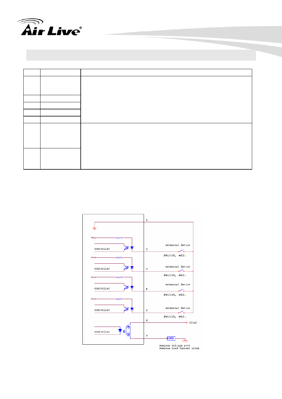
A user can refer to the schematic below to make a proper connection between I/O
connector and external sensor and output device.
z
Explanation of External I/O Circuit Diagram:
Application 1