2 cable installation, 3 order of commissioning steps – ADS-TEC VMT5010 (2010) User Manual
Page 20
Terminals VMT5010
20
© ads-tec GmbH • Raiffeisenstr.14 • 70771 Leinfelden-Echterdingen
4.2 C
ABLE INSTALLATION
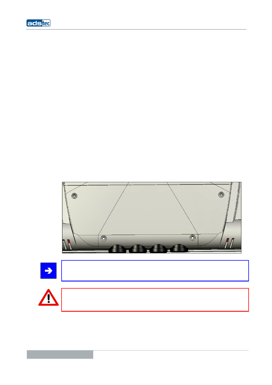
The power supply connectors and interfaces of this device are installed inside the case.
Cables can be routed through rubber grommets and exit the case on the bottom. The
grommets are inserted between the case and the cover, and can easily be removed after
removing the cover. Since this device includes the required input peripherals (soft
keyboard / touch screen), only one grommet for the power supply cable (cable diameter of
6...7mm) as well as three blank plugs are integrated by default. Should it be required to
feed through more cables from the device to the outside, these blank plugs must be
replaced by suitable grommets (optionally available accessories).
Pos: 18 /Datentechnik/Inbetriebnahme/Reihenfolge der Inbetriebnahme/Reihenfolge der Inbetriebnahme für VMT 50xx-Serie @ 0\mod_1158848845491_681.doc @ 803 @
4.3 O
RDER OF COMMISSIONING STEPS
•
Remove the case cover screws and carefully remove the cover.
•
Fix the wires of the power supply cable in the screw terminals by using Phoenix
Combicon in wire end sleeves.
•
Plug the data cable connector on the desired interface connector and screw it on,
if possible.
•
Select a cable grommet with a suitable diameter for each cable to be fed through,
and enclose the cable with it. Additionally there are cord grips for different cable
sizes available.
•
Remove the blank plug and replace it with the grommet surrounding the cable.
•
Attach the case cover properly and install the screws.
Note:
The service slot is fixed with captive screws.
Warning:
Full protection according to the indicated protection class is only ensured if the case cover
is properly installed!
Pos: 19 /Datentechnik/Inbetriebnahme/Betriebsbereitschaft prüfen/Betriebsbereitschaft prüfen für OPC/CPC/PLC/OTC/ITC/VMT-Serie(+Monitore) / IPC 5100/5500/2400/1100 @ 0\mod_1158905578361_681.doc @ 806 @