Echo 73711S Instruction v.1 User Manual
Page 3
INSTRUCTION SHEET
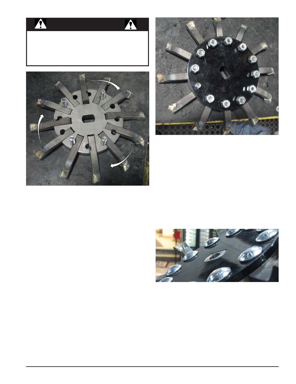
Top view of spacer plates with blades in place and properly oriented so
the blade tips point in a clockwise direction.
Bottom view of cutter assembly with the
spindle mounted flush to bottom plate.
4. There are four straight cutting blades and eight angled
blades.
5. The angled blades are shorter than the straight blades
and are placed next to each other with a straigh blade
placed next. Continue until all 12 blades are in place.
6. Put all of the remaining bolts into the holes from the
bottom.
7. Place the painted cover plate (76900-12) over and on
to the 12 bolts of the assembly and secure plate into
place using the twelve 3/8" lock nuts (15388).
8. Install the cutter assembly on to the spindle, making
sure the angled blades point down. Also make sure the
end of the spindle is flush with the bottom plate and
secure into place using the 1/2 X 3/4" bolt and washer
removed in step 1 of the disassembly. Torque bolt to
70 ft. lbs.
IT IS IMPORTANT TO NOTE THE SPECIFIC
SEQUENCE AND ORIENTATION THE BLADES
MUST BE IN FOR SUCCESSFUL ASSEMBLY
AND OPERATION OF THE SUTTER SYSTEM.
NOTE