4 replacing the wear liner, 5 unplugging the rotor, 6 unplugging the inlet hose – Echo DL10570 Owners Manual v.4 User Manual
Page 15
8 & 10 Inch Debris Loaders
11
SERVICE & MAINTENANCE
BEFORE INSPECTING OR SERVICING ANY PART OF THIS MACHINE, SHUT OFF POWER SOURCE,
AND MAKE SURE ALL MOVING PARTS HAVE COME TO A COMPLETE STOP.
WARNING
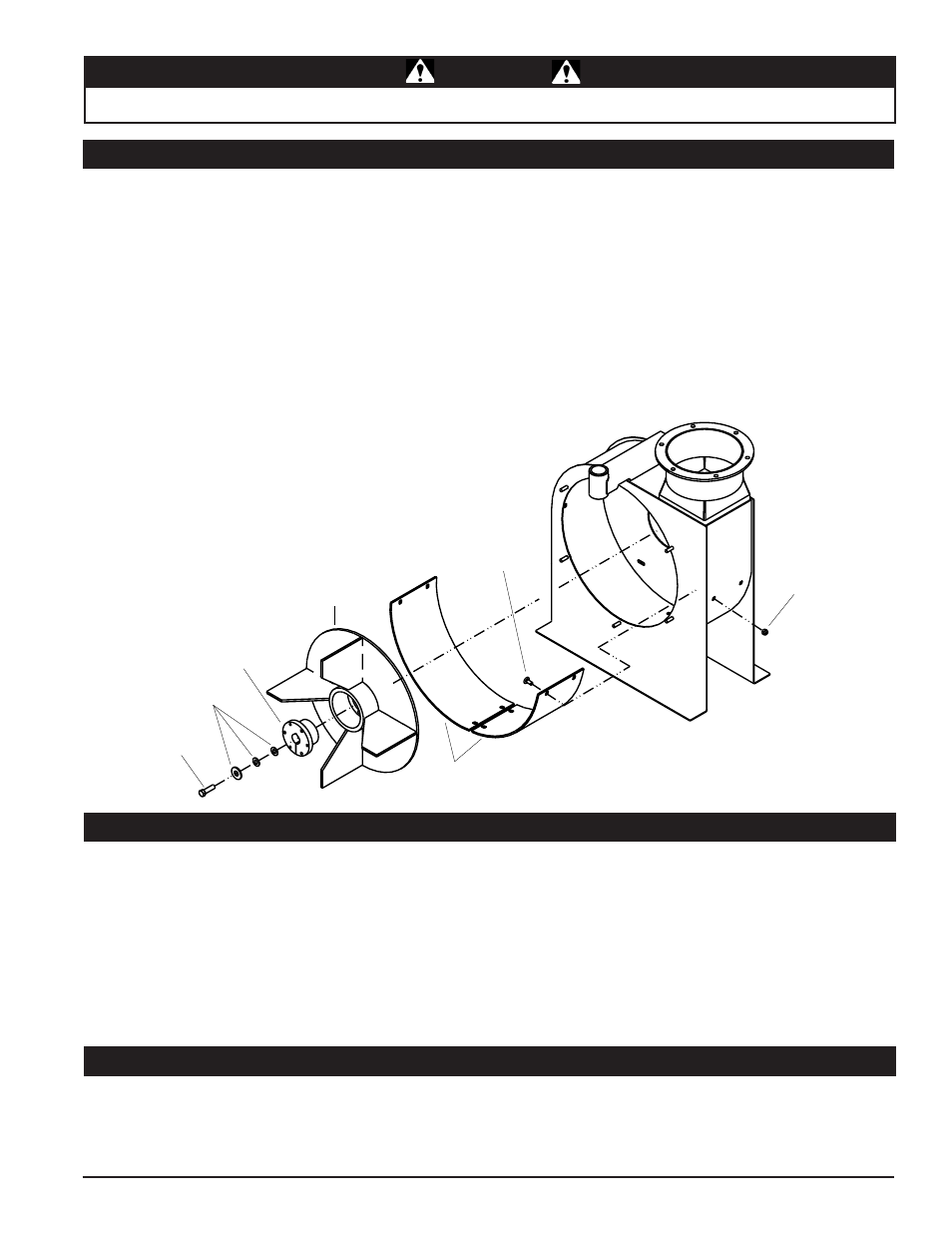
5.4 REPLACING THE WEAR LINER
The fan housing wear liners are replaceable on 390cc &
570cc engine models. To replace the wear liners:
1. Shut off engine and allow rotor to completely stop.
2. Remove the fan intake weldment from the fan
housing.
3. Remove the 7/16 x 1-1/2" bolt and washer from the end
of the engine crank shaft.
4. Remove the bushing and rotor from the engine crank
shaft.
5. From the outside of the debris loader housing, remove
eight 5/16" nylock nuts that hold the two wear liners.
WEAR
LINERS
ROTOR
BUSHING
7/16” x
1-1/2” BOLT
WASHERS
5/16” x 3/4”
CARRIAGE
BOLT
5/16”
NYLOCK NUT
The debris loader is designed to be used in fairly dry
conditions. Wet material, along with too much debris and
large sticks, can plug the rotor or hose. A plugged rotor
bogs down the engine and can possibly stop the engine if
the rotor is severely plugged. To clear the rotor:
1. Shut off engine and allow rotor to completely stop.
2. Remove spark plug wire.
3. Loosen the six 5/16" nuts that hold the intake weldment
to the debris loader frame.
5.5 UNPLUGGING THE ROTOR
1. If the hose becomes plugged during operation,
straightening the hose may dislodge the clog.
2. If straightening the hose does not work, shake the hose
in an up and down or side to side motion.
5.6 UNPLUGGING THE INLET HOSE
6. Remove the old wear liners and insert the new liners.
7. Install the new wear liners with eight 5/16 x 3/4" carriage
bolts and nylock nuts. Feed the carriage bolts from
inside the debris loader housing. Torque hardware to
17 ft-lbs.
8. Reinstall the bushing and rotor on the engine crank
shaft.
9. Reinstall the 7/16 x 1-1/2" bolt and washer to the engine
crank shaft. Torque to 50 ft-lbs.
10. Make sure approximately 1/4" clearance exists between
the fan housing and the rotor plate.
4. Turn the vacuum intake clockwise to remove it.
5. Check the hose for clogs and clear debris from the
rotor.
6. Turn the rotor by hand to verify it is unplugged.
7. Place the intake weldment over the six frame nuts and
turn it counterclockwise to set the studs in the weldment
notches. Tighten 5/16" nuts to 17 ft-lbs.
8. Reconnect spark plug wire and resume operation.
3. If the clog remains after performing the above two steps,
shut the engine off and wait for all moving parts to stop
moving. Then, remove the hose from the fan housing
and manually unplug the hose.