7 connect control cable, 8 attach discharge tube, 9 install the battery – Echo 72928 Owners Manual v.5 User Manual
Page 14: Important
9 INCH CHIPPER
12
ASSEMBLY
2.9 inSTall The baTTerY
The chipper is not shipped with a battery. Use group
1.
22F 300 CCA minimum.
Mount the battery in the battery box located next to
2.
the fuel tank. Connect the positive battery cable to
the positive terminal and the negative cable to the
negative terminal.
imPorTanT
If any bolts or nuts are dropped in the machine, be
sure to remove them before starting the machine.
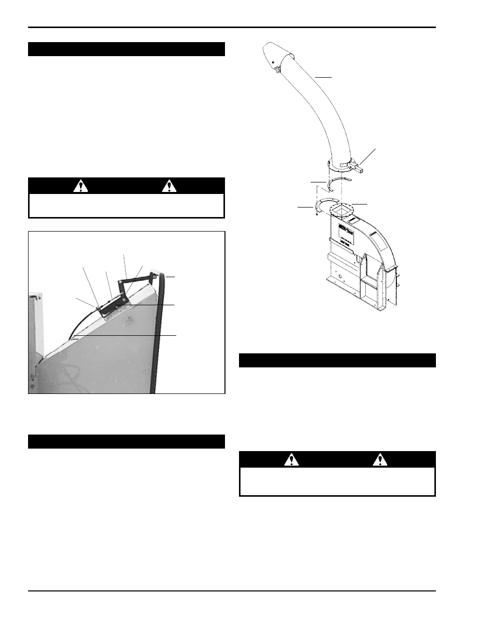
2.8 aTTach diScharge Tube
Attach the blower discharge tube to the chipper frame
1.
mounting flange. Slide the discharge tube clamp un-
derneath the mounting flange (Figure 2.7).
Install the second half of the spacer and clamp (in-
2.
cluded in owner's kit) to the tube and flange with 3/8"
x 1-1/4" bolts and nuts. Rotate the tube 360 degrees
to make sure it is mounted correctly. lock it in place
with the lock pin.
BLOWER
DISCHARGE
TUBE
MOUNTING FLANGE
SPACER
DISCHARGE CLAMP
LOCK LEVER
Figure 2.7, Attaching the discharge tube
2.7 connecT conTrol cable
Remove the clevis assembly from the hydrostatic
1.
control cable end (see Figure 2.6). Remove one nut
on the cable end. Insert the cable end into the hole
in the cable anchor weldment. Replace the nut and
clevis assembly.
Attach the clevis assembly to the center hole on the
2.
feed control lever.
Adjust the cable detent ball to contact the detents in
3.
the cable anchor weldment when the control arm is in
the forward or reverse position.
imPorTanT
See Section 3 for hydrostatic pump start-up proce-
dure.
INSERT CABLE
THROUGH HOLE
NUT
CLEVIS
ASSEMBLY
DETENT
BALL
CONTROL
ARM
CABLE ANCHOR
WELDMENT
HYDROSTAT
CONTROL
CABLE
FEED
CONTROL
LEVER
Figure 2.6, Control cable components