8 drive belt adjustment – Echo CH45342 Owners Manual v.3 User Manual
Page 22
4.5 INCH CHIPPER
18
SERVICE & MAINTENANCE
BEFORE INSPECTINg OR SERVICINg ANy PART OF THIS MACHINE, SHuT OFF POWER SOuRCE,
DISCONNECT SPARk Plug WIRE FROM SPARk Plug AND MAkE SuRE All MOVINg PARTS HAVE COME TO A COMPlETE STOP.
WaRNING
Check the condition of the drive belt(s) annually or after
every 25 hours of operation, whichever comes first. Replace
a cracked, frayed, worn or stretched drive belt. Only replace
drive belt with original banded type belt. Do not use single
type belts. To adjust the drive belt(s), proceed as follows:
5.8.1 ENGINE modELS
place the chipper engagement lever in the StaRt
1.
position.
Shut engine off.
2.
Disconnect battery cables (electric start models).
3.
Remove the seven 5/16 x 3/4" bolts securing the
4.
belt shield to the shield weldment. Remove the belt
shield.
to
5.
increase tension on the belt, do the following:
Move the engagement lever to the CHIppInG
a.
position.
loosen the four carriage bolts attaching the engine
b.
plate to the trailer.
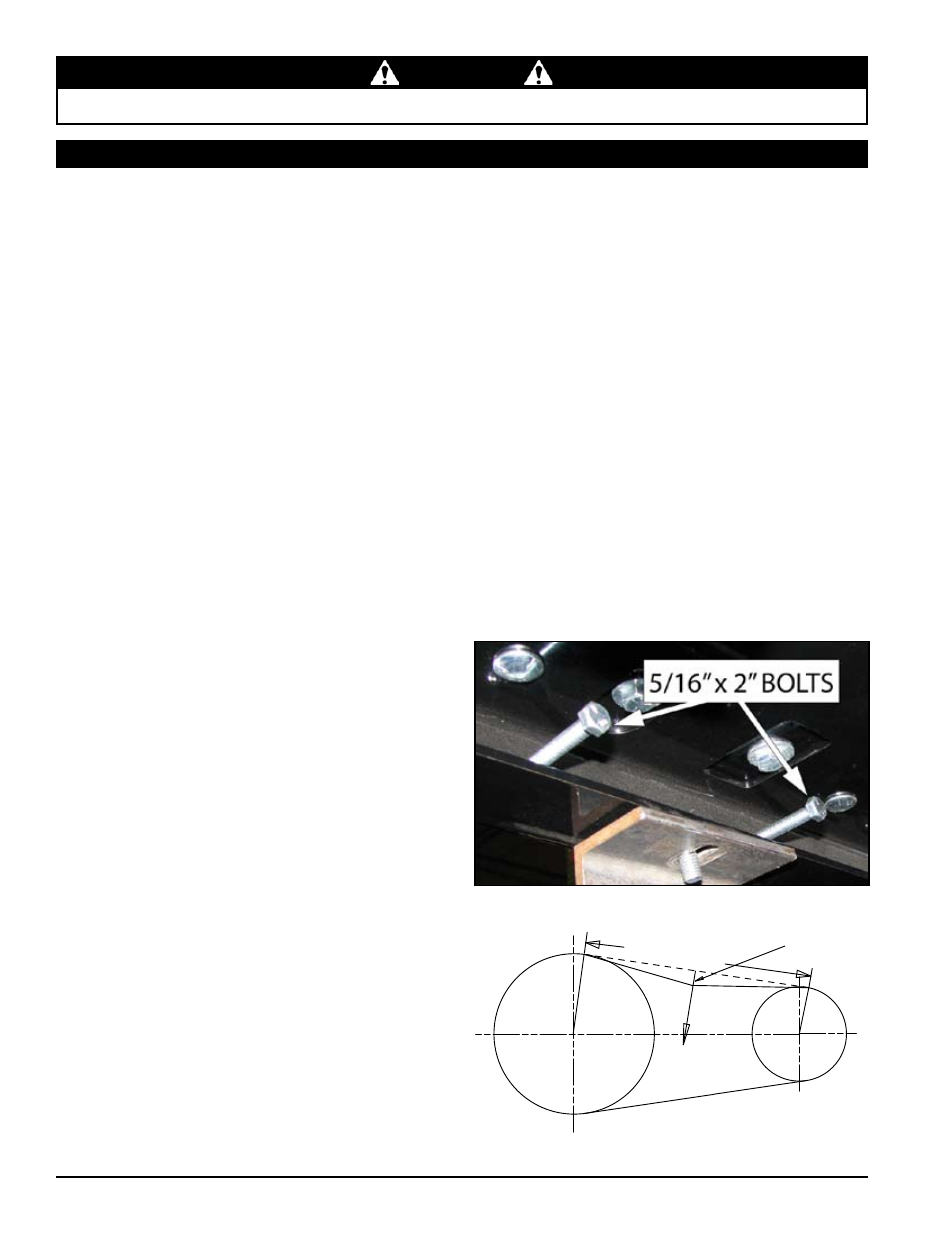
locate the two 5/16 x 3" bolts and 5/16" flange
c.
nuts located on the side of the chipper between the
trailer and the engine plate (Figure 5.3).
Tighten both 5/16" bolts equally to move the
d.
engine away from the chipper housing until the
belt deflection is about 7/16" when a 20 lb. load is
placed against the belt.
Tighten the four carriage bolts securing the engine
e.
plate to the trailer.
Tighten both 5/16" flange nuts to ensure the proper
f.
deflection is maintained.
to
6.
loosen tension on the belt, do the following:
Move the engagement lever to the CHIppInG
a.
position.
loosen the four carriage bolts attaching the engine
b.
plate to the trailer.
loosen both 5/16" flange nuts.
c.
loosen both 5/16 x 3" adjustment bolts equally and
d.
push the engine plate against the bolts. loosen
bolts until the belt deflection is about 7/16" when
a 20 lb. load is placed against the belt.
Tighten the four carriage bolts securing the engine
e.
plate to the trailer.
Tighten both 5/16" flange nuts to ensure the proper
f.
deflection is maintained.
5.8 dRIvE bELT adJuSTmENT
If the bolts and nuts between the engine plate and the
7.
trailer cannot be adjusted any further, and the tension
needs further adjustment, tighten the eyebolt until the
appropriate deflection is achieved.
Replace the belt if no adjustment is left (Section 5.9).
8.
Reinstall the belt shield.
9.
5.8.2 pTo modELS
Move the engagement lever to the RElEASE
1.
position.
Disengage PTO and shut off tractor engine.
2.
Remove the PTO shaft from the tractor and disconnect
3.
from the 3 point hitch.
Move the engagement lever to the CHIppInG
4.
position.
Remove the 5/16" bolts to take off either the front or
5.
rear belt shield.
Either tighten or loosen the eyebolt at the base of the
6.
idler until the belt deflection is about 7/16" when a 20
lb. load is placed against the belt.
Reinstall belt shields.
7.
Figure 5.3, adjustment bolts
SPAN LENGTH
FORCE
20 LBS
7/16" DEFLECTION