Assembly, Warning – Echo CH6614 Owners Manual v.3 User Manual
Page 10
6 INCH CHIPPER
6
Section
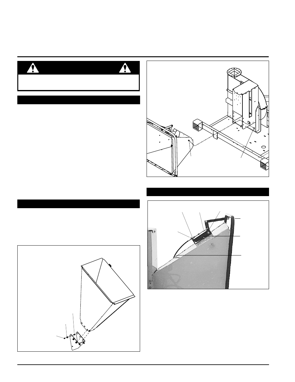
2.2 aTTach chIppER chuTE
Mount the chipper chute to the frame mounting bracket
1.
using eight carriage bolts and locknuts (see figures
2.1 or 2.2). use three bolts on each side and two on
the bottom.
Tighten bolts to 35 ft-lbs.
2.
1-1/2” CARRIAGE BOLT
3/8” WASHER
3/8” NYLOCK NUT
Fig. 2.1, Attaching the chipper chute to the gravity feed model
aSSEmbLY
2.1 TRaILER WhEELS aNd hITch
2
2.3 coNNEcT ThE coNTRoL cabLE
INSERT CABLE
THROUGH HOLE
NUT
CLEVIS
ASSEMBLY
DETENT
BALL
FEED
CONTROL
LEVER
CABLE
ANCHOR
WELDMENT
HYDROSTAT
CONTROL
CABLE
Remove the clevis assembly from the hydrostatic
1.
control cable end (see Fig. 2.3). Remove one nut on
the cable end. Insert the cable end into the hole in the
cable anchor weldment. Replace the nut and the clevis
assembly.
Attach the clevis assembly to the center hole on the
2.
feed control lever.
Adjust the cable detent ball to hold the control arm in
3.
the forward position or neutral position detents.
Fig. 2.3, Control Cable Assembly
1-1/2” CARRIAGE
BOLT
3/8” NYLOCK
NUT
modEL ch6614
modEL ch6614h
Fig. 2.2, Attaching the chipper chute to the hydraulic feed model
Remove the chipper from its shipping crate. Place the
1.
unit on a level surface before attempting to assemble
it. See the torque chart in the back of the manual for
tightening torque of bolts and screws.
Raise the trailer several inches from the ground with a
2.
hoist or jack. Support the chipper securely.
lift one wheel to a hub and align the wheel lug holes
3.
with the hub lug bolts. Thread the lug nuts (found in
the parts kit) onto lug bolts and tighten the lug nuts to
75 ft. lbs. Follow a star pattern when tightening the lug
nuts. Repeat this step for the remaining wheel.
Mount the trailer hitch assembly to the frame using
4.
three 3/8" x 3-1/2" bolts and locknuts.
If any bolts or nuts are dropped in the machine, be
sure to remove them before starting the machine.
WaRNING