Installation, 1 cables recommended for dmx512, 2 terminal resistor (bus termination) – Behringer Eurolight 24-Channel DMX Lighting Console LC2412 User Manual
Page 20: 3 pin assignment
20
EUROLIGHT LC2412 User Manual
DMX channels
A DMX channel consists out of one digitally transmitted information unit
(1 Byte/8 Bit), whereas 256 different information units can be transmitted.
These units are transmitted sequentially, that is, channels 0 and upwards
on the sender are accounted for, and the respective information units are
assigned. The sequence then starts anew at the next channel. In the worst-case
scenario (all 512 channels are in use) the refresh rate has the value of 44.1 Hz.
You can derive from this that it is advisable to only use as many channels as you
actually need.
Since there are 24 channels with adjustable illumination (to each of which 3 DMX
channels can be assigned), there is a total of 72 DMX channels that can be laid
out. Additionally, there are two special channels, each of which can switch a
maximum of 2 DMX channels on and off.
To assign the desired DMX channels to individual console channels (or to preview
the assignment of channels), go through the following steps:
1. Press the UTILITY 2 key.
Fig. 8.2: Display “DMX Patch 1”
2. Select “DMX PATCH” using the SOFT A key.
Fig. 8.3: Display “DMX Patch 2”
The console channel is shown in the top left portion of the menu.
The connected DMX channels are shown to its right (standard setting
is 1:1. Example: Console channel 01 is connected to DMX channel 000,
console channel 08 is connected to DMX channel 07, etc.).
The DMX channel is shown in the lower left line; its status is shown next to it
(NU = Not Used or USE 1...512). In our example DMX channel 000 is connected to
console channel 01.
3. Use the Flash keys to first select the console channel to which you wish to
assign a DMX channel (channels13 - 24: switch to upper mode, SPECIAL 1
(channel 25) and SPECIAL 2 (channel 26) by pressing (8) and (9)).
4. Select a DMX channel usign the DATA wheel.
If this DMX channel is already occupied, this will be shown in the display
together with the respective console channel number. Select the console
channel (Flash key), and select “OPEN” (SOFT B key). Start again at step 3.
Alternatively, you can also select a different DMX channel.
5. Press the SOFT A key (“CONNECT” option) and connect the console channel
with the DMX channel. If you wish to connect multiple DMX channels with
the same console channel, simply select an additional DMX channel and
proceed with the connection as previously described.
6. Use the QUIT key to go back to the main menu.
Connecting channels 1:1 (one-to-one) or disengaging
all connections
1. Perform steps 1 and 2, as described under 8.2.3.
2. Press the SHIFT key (37).
Fig. 8.4: Display “DMX Patch 3”
3. Now, select “ALL CLEAR” using the SOFT B key to disengage all connections.
Use SOFT A to go back to the standard setting, “ALL 1:1.”
9. Installation
You will need various types of cables for different applications. The following
illustrations show you how to lay out these cables. Always use only high-grade cables.
9.1 Cables recommended for DMX512
The cables should be manufactured according to EIA-485 or EIA-422
specifications. Using shielded, twisted, double-stranded data transmission cables
is recommended. For example, these are the same cables used for transmitting
digital audio data in the AES/EBU format. You can also implement lines with a
second wire set, used as a replacement in case of a malfunction.
Using high-quality mic cables is also possible, but their length shold be limited to
500 m due to the high cable capacity near a data line.
9.2 Terminal resistor (Bus Termination)
Using a termnal resistor at the end of the line is an additional condition needed for
glitch-free data transmission. To this end, a 120-Ohm resistor is located between
both conductors (Pin 2 and Pin 3) in an extra connector. Connect this connector
to the DMX out connector of the last piece of equipment in the DMX chain.
Shorter connections (up to several meters/roughly 15 ft) do require termination.
9.3 Pin assignment
9.3.1 DMX512 connections
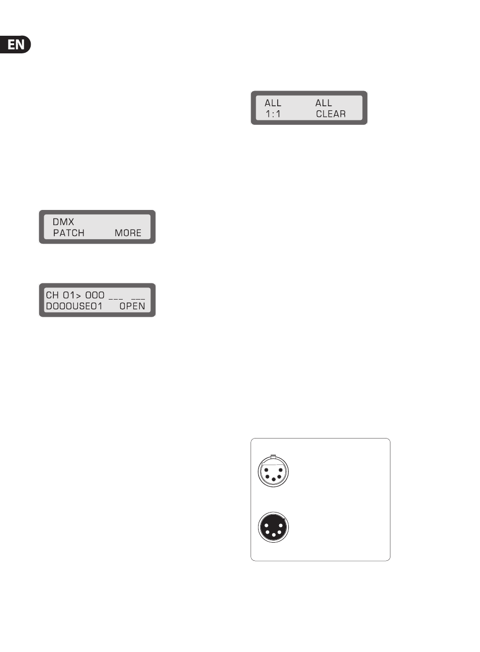
The DMX512 norm mandates the use of 5-prong XLR connectors. The correct
layout is shown in fig. 9.1.
1 = Signal common/shield
2 = Data 1 (-)
3 = Data 2 (+)
5-pin XLR connectors for DMX512 signals
Pins 4 (data 2 -) and 5 (data 2 +) are not connected (optional use)
Fig. 9.1: 5-prong XLR connector for DMX512 connections