Voltmeter adjustment, 15 throttle checks and adjustments, Voltmeter adjustment -41 – JLG 150HAX Service Manual User Manual
Page 79: Throttle checks and adjustments -41, Tilt switch adjustment - voltmeter -41
SECTION 3 - CHASSIS & TURNTABLE
3120817
– JLG Lift –
3-41
Voltmeter Adjustment
8.
Park machine on a flat, level surface. Ensure
machine is level and tires are filled to rated pressure.
9.
If engine is not running, turn ignition switch to ON.
10.
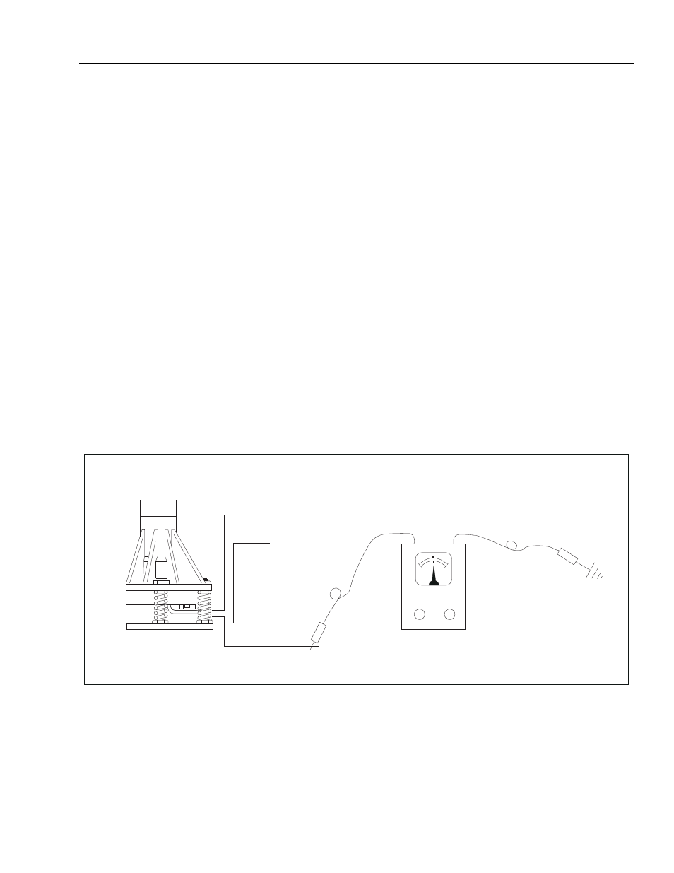
Connect black lead of voltmeter to ground and red
lead to yellow wire protruding from pot on bottom of
sensor.
11.
Adjust leveling nuts to obtain the highest possible
voltage reading.
12.
Check voltage at trip point in all four directions. If
voltage reading is not symmetrical, repeat step (4)
above.
3.15 THROTTLE CHECKS AND ADJUSTMENTS
NOTE: Never run fuel tank dry. Diesel engines cannot be
restarted after running out of fuel until fuel system
has been air-vented or “bled” of air. See Cummins
instruction manual for procedure.
a. Disconnect actuator cable from throttle lever.
With the aid of an assistant, start the engine and
allow it to come up to operating temperature.
Adjust throttle lever stop until engine runs at
1800 RPM. Shut down engine. Reattach actuator
cable to throttle lever, making sure that low (mid)
engine setting remains the same. If necessary,
adjust slide pin to contact low (mid) engine limit
switch at 1800 RPM. Shut down engine.
b. Disconnect power (red) wire from high drive
dump valve at rear of valve compartment. With
the aid of an assistant, start engine from basket
and allow to come up to operating temperature.
Activate footswitch. Turn on HIGH ENGINE
switch. Hold drive controller in full drive position.
Adjust slide pin to contact high engine limit
switch at 2500 RPM. Shut off all switches and
controllers. Re-connect power (red) wire to high
drive dump valve.
NOTE: Actuator cable travel must stop slightly before lever
makes contact with throttle lever stop. Failure to do
so will burn out actuator.
YELLOW
BLACK
WHITE
RED
Figure 3-27. Tilt Switch Adjustment - Voltmeter