6 pressure setting procedures, Low drive system, Pressure setting procedures -11 – JLG 150HAX ANSI Service Manual User Manual
Page 107
SECTION 5 - HYDRAULICS
3120679
– JLG Lift –
5-11
5.6 PRESSURE SETTING PROCEDURES
Cold temperatures have a significant impact on pressure
readings. JLG Industries, Inc. recommends operating the
machine until hydraulic system has warmed to normal
operating temperatures prior to checking pressures. It is
also recommended that a calibrated gauge is used. Pres-
sure readings are acceptable if within ±5% of specified
pressures.
Low Drive System
NOTE: Make all drive pressure adjustments with pressure
gauge plugged into quick-connect on the propor-
tional relief and dump valve.
1.
Sequence Pressure.
a. Using a suitable “hot wire”, activate dump valve.
b. Loosen locknut on sequence valve and adjust to
450 psi (31 bar). Turn adjusting screw clockwise
to increase pressure, counterclockwise to
decrease pressure. Tighten locknut and remove
“hot wire” from dump valve.
2.
Single Stack Proportional Valve.
NOTE: Prior to adjusting drive pressure, plug brake port (S)
on drive counterbalance valve, located inside frame
beneath swing bearing.
a. Bottom out Drive function.
b. Loosen locknut on adjusting screw on propor-
tional relief and dump valve and adjust to 3200
psi (221 bar). Turn screw clockwise to increase
pressure, counterclockwise to decrease pres-
sure. Tighten locknut.
5 Stack Directional Control Valve (Internal
Relief Adjustment)
NOTE: Make all pressure adjustments with pressure gauge
plugged into quick-connect adjacent to high drive
dump valve at rear of valve compartment.
1.
Test the hydraulic pressures:
a. Start the engine and stall each function. Record
the pressures.
b. Shut off the engine and apply a vacuum to the
hydraulic tank.
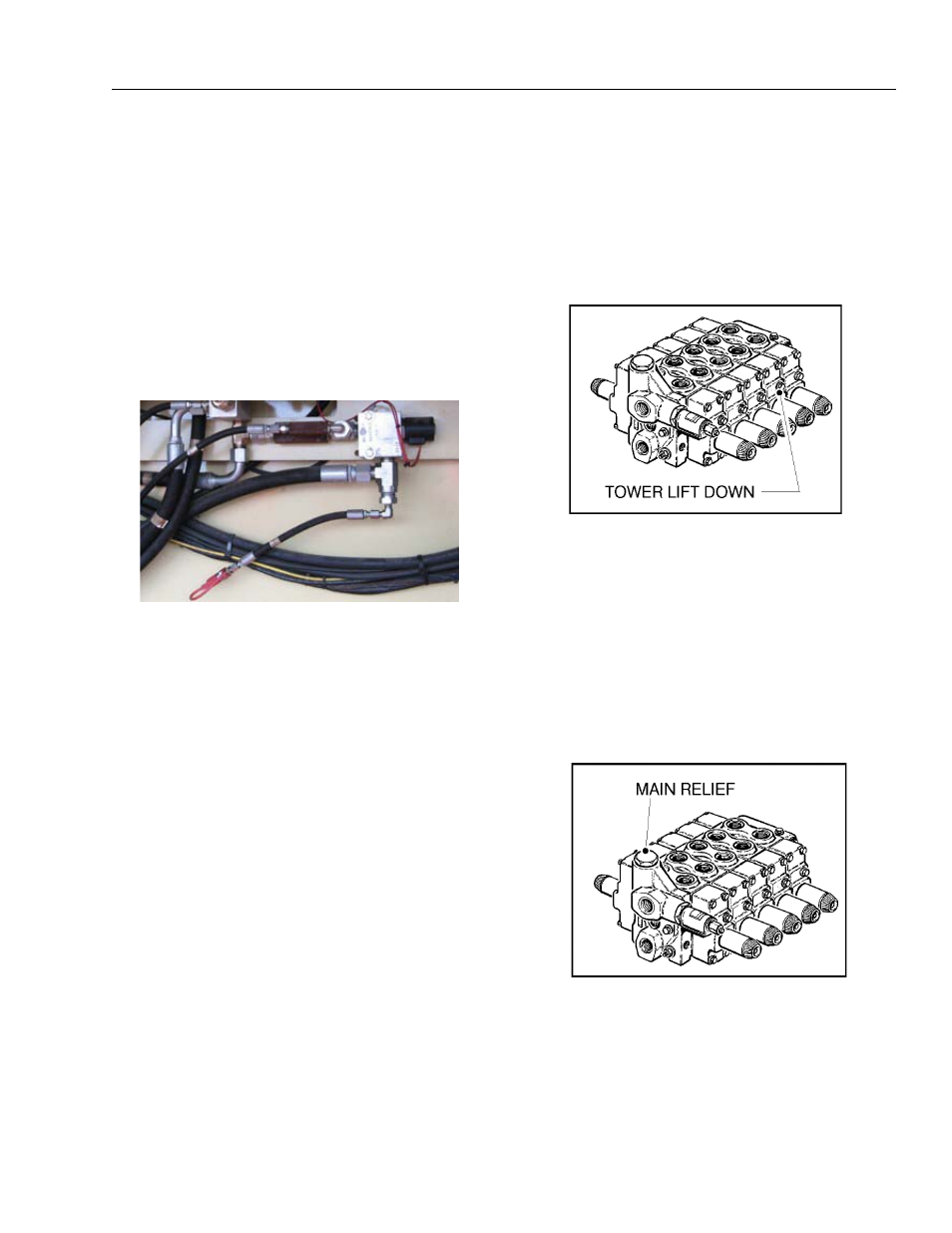
c. Remove the plug cap from the Tower Lift Down
valve section and add 6 shims. Reinstall the cap
and remove the vacuum from the hydraulic tank.
d. Start the engine and stall the Tower Lift Down
function. Record the main relief pressure.
e. Shut off the engine and apply a vacuum to the
hydraulic tank.
f. Remove the plug cap from the Tower Lift Down
valve section and remove the 6 shims. Reinstall
the cap and remove the vacuum.
2.
Adjust the hydraulic pressures:
a. Shut off the engine and apply a vacuum to the
hydraulic tank.
b. If the main relief pressure is incorrect, replace
the main relief cartridge in the inlet section.
c. To adjust the functions, identify the correct plug.
d. Remove the plug and add shims to increase
pressure or remove shims to decrease pressure.
Each shim added or removed will change the
pressure setting approximately 150 psi (10 Bar)