JLG 20VP (3120727) Operator Manual User Manual
Page 36
SECTION 4 - MACHINE OPERATION
4-2
– JLG Lift –
3120727
4.3
MACHINE OPERATION
The following sequence of basic procedures must be fol-
lowed to safely operate the machine.
1.
At the ground control station, set power PLAT/OFF/
GRND key switch to the PLAT position to operate
from platform controller, or GRND to operate from
ground controls.
2.
Check that the EMERGENCY STOP button at the
ground and platform controls are in the RESET posi-
tion for operation. Also check that EMERGENCY/
MANUAL DECENT CONTROL VALVE is CLOSED
(lower access hole in rear cover).
NOTE: 20VP MACHINES WITH THE UL-EE OPTION ONLY -
These machines are equipped with a master ON/
OFF switch mounted on the rear cover of the
machine. This switch must be set to the ON position
to operate the machine.
3.
Check LED strip on the platform controller for cur-
rent battery charge level before operating lift to be
certain charge is sufficient to complete your work
task. If the battery charger is plugged into an AC
outlet, drive functions on the machine will be locked
out.
NOTE: If LED’S are flashing a fault code on the platform
controller box at machine power-up, see Section-3,
“Troubleshooting” of the Service and Maintenance
Manual for information on reading fault codes.
WORK AREA MUST BE A SMOOTH, FIRM AND LEVEL SURFACE
FREE OF HOLES, LARGE CRACKS OR DEBRIS ON SURFACE.
THE WORK SURFACE MUST BE CAPABLE OF SUPPORTING THE
WEIGHT OF THE MACHINE PLUS THE PLATFORM’S MAXIMUM
RATED LOAD CAPACITY. ALWAYS CHECK THE BUBBLE LEVEL
INDICATOR ON BASE FRAME TO BE SURE MACHINE IS LEVEL
BEFORE RAISING PLATFORM.
4.
Inspect work area before operating lift.
Platform Loading
The platform maximum rated load capacity is displayed
on a decal located on the platform. The maximum rated
load capacity includes the combined weight of the opera-
tor and any materials, tools, etc. placed in the platform
with the operator.
Maximum rated load capacity for all platforms (Except
Extendible) is as follows:
* Extendible Platform available only for 20VP.
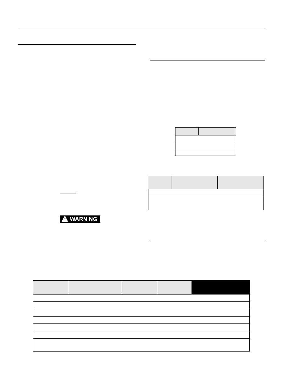
Interlock Switch Operating Conditions
Table 4-3. shown, lists machine response to various inter-
lock switch positions.
Table 4-1. Maximum Rated Load Capacity
(for all platforms except Extendible)
Model
Max. Capacity
10VP
350 lb. (159 kg)
15VP
350 lb. (159 kg)
20VP
350 lb. (159 kg)
Table 4-2. Maximum Rated Load Capacity
(for Extendible Platform*)
Model
Max. Capacity
(ANSI - U.S.A.)
Max. Capacity
(C.S.A. - Canada)
10VP
Not Available*
Not Available*
15VP
Not Available*
Not Available*
20VP
350/300 lb. (160/135 kg)
350/250 lb. (160/114 kg)
Table 4-3.
Machine Interlock Switch Operating Conditions.
Elevation/
Speed Switch
Drive Cutout
(PHP System)
Tilt Status
Brake Status
Controller Response
mast retracted
bars raised
(not tilted)
engaged
Full Drive and Lift
mast retracted
bars raised
(not tilted)
disengaged
Drive and Lift disabled
mast extended
bars lowered
(not tilted)
engaged
Drive 25% maximum
mast extended
bars lowered
(not tilted)
engaged
Drive disabled
mast retracted
bars raised
(tilt)
engaged
Lift disabled
mast retracted
bars raised
(tilt)
disengaged
Drive and Lift disabled
mast retracted
bars raised/battery charger
plugged-in
(not tilted)
engaged
Drive disabled