Table 3-17. e-stop and key switch circuit check, E-stop and key switch circuit check -27 – JLG 20VP (3120728) Service Manual User Manual
Page 87
SECTION 3 - TROUBLESHOOTING
3120728
– JLG Lift –
3-27
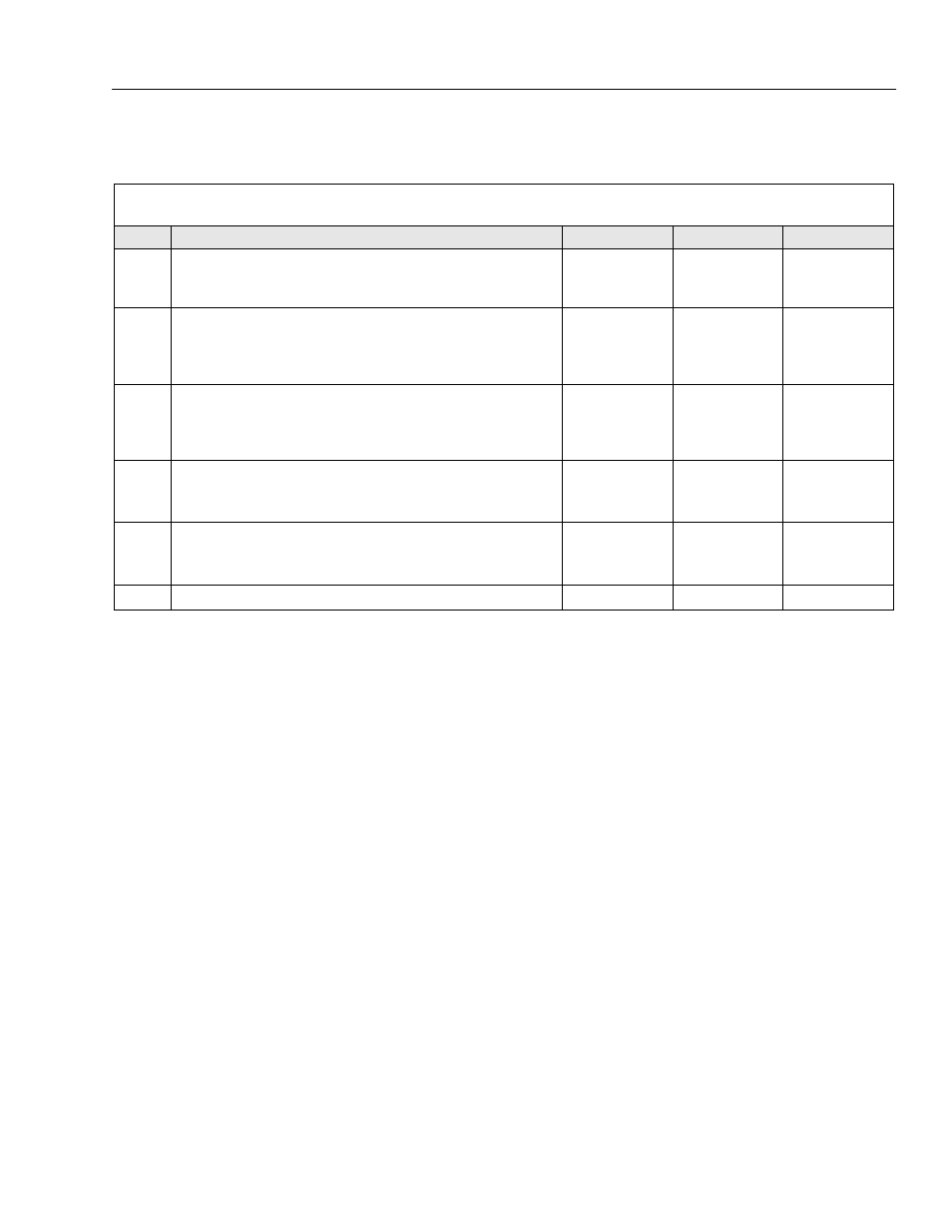
Table 3-17. E-Stop and Key Switch Circuit Check
• Batteries Fully Charged. (24 Volts)
• Ground Control Key Switch set to the Platform or on Ground position and the Emergency Stop Switch Reset to ON.
STEP
ACTION
SPEC
YES
NO
1.
KEY SET TO PLATFORM: Check voltage on the Yel/Red, 2-2 wire
from the emergency stop switch to MC-1 controller box, pin 3 in the
X101 connector and pin 30 on the Power Relay.
24 Volts
Circuit is OK
Go to Step 2
2.
KEY SET TO GROUND: Check voltage on the Yel/Red, 2-4 wire com-
ing out of the ground control box assembly to pin 87 on the power
relay, and main contactor. Yel/Red 2-8 wire to pin 86 on the ground
relay.
24 Volts
Circuit is OK
Go to Step 3
3.
Open the Ground Control Box Assembly (housing with key switch
and E-stop switch mounted inside) and check the voltage on the Yel/
Red, 2-1 wire leading into the emergency stop switch from the Key
switch.
24 Volts
Repair connec-
tion to or replace
E-Stop switch
Go to Step 3
4.
Check voltage on the Red, 1-1 wire leading into the Key switch.
24 Volts
Repair connec-
tion to or replace
key switch
Go to Step 4
5.
Check voltage and continuity through the 5 amp fuse mounted inline
outside of the ground control box assembly, on the Red, 1-1 wire.
24 Volts
Go to Step 6
Replace Fuse or
Fuse Holder if
damaged
6.
Check connection at battery.
24 Volts
Circuit OK
N/A